ISOLATED OUTPUT WIRING DIAGRAMS
50 or 60 Hz
100/200, 110/220, 115/230, or 120/240V Out
with Isolated Output Option
Menu 4 2 4 set to 200, 220, 230, or 240, as required.
X1 | X3 |
| X0 |
|
| X2 | |||||
|
|
|
|
|
|
|
|
|
|
|
|
X |
|
| X | X | |||||||
|
|
|
|
|
| ||||||
|
|
|
|
|
|
|
|
|
|
| |
|
|
|
|
|
|
|
|
|
|
| |
|
|
| 100, 110, |
| 100, 110, |
|
|
| |||
|
|
| 115, or 120 |
|
|
| 115, or 120 |
|
| ||
|
|
|
|
|
|
|
|
|
|
|
|
|
|
| 200, 220, 230, or 240 |
|
| ||||||
L1 |
|
| N | L2 | |||||||
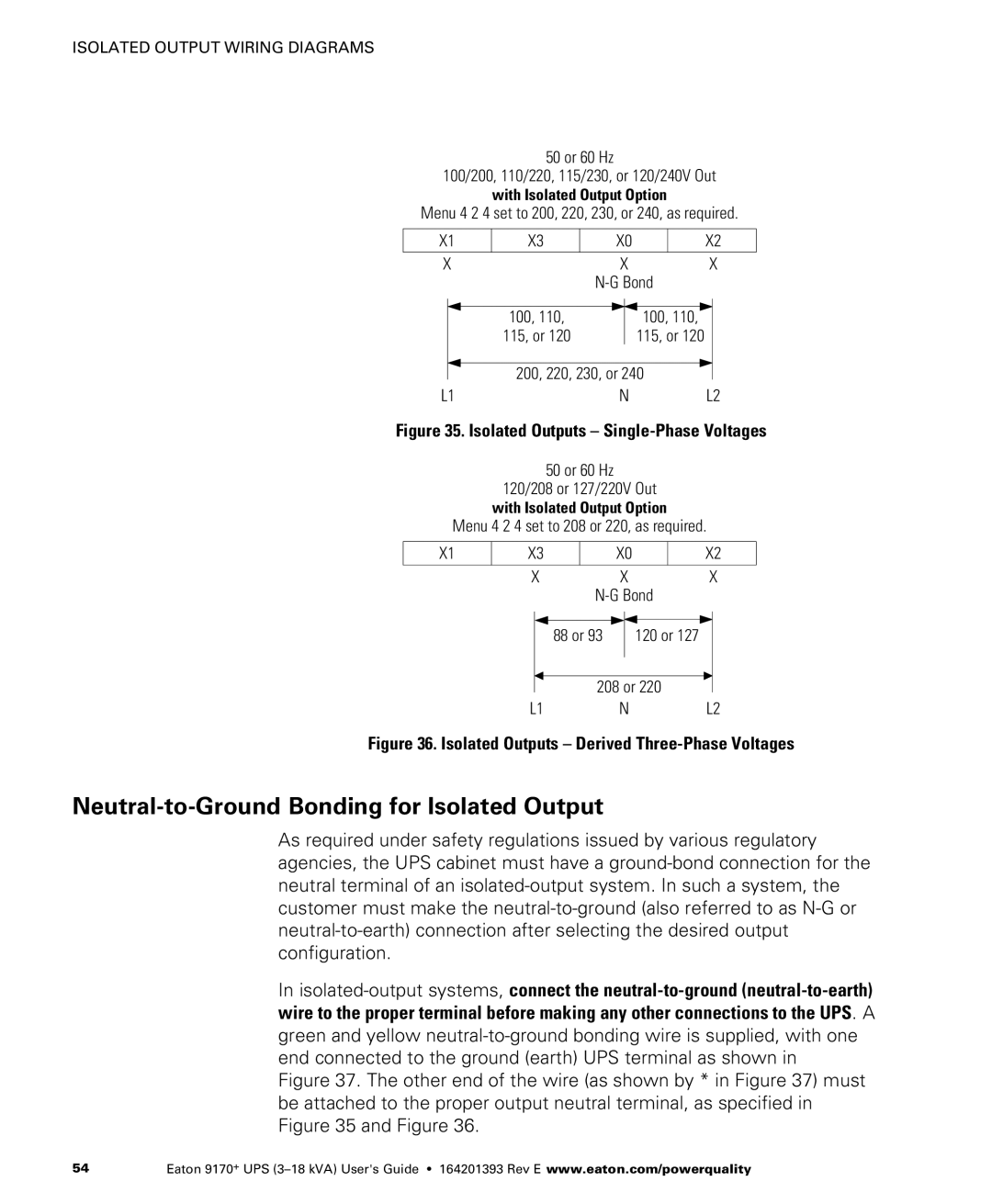
Figure 35. Isolated Outputs – Single-Phase Voltages
50 or 60 Hz
120/208 or 127/220V Out
with Isolated Output Option
Menu 4 2 4 set to 208 or 220, as required.
X1 | X3 | X0 | X2 |
|
|
|
|
| X | X | X |
|
|
|
88 or 93
120 or 127
208 or 220
L1NL2
Figure 36. Isolated Outputs – Derived Three-Phase Voltages
Neutral-to-Ground Bonding for Isolated Output
As required under safety regulations issued by various regulatory agencies, the UPS cabinet must have a
In
Figure 37. The other end of the wire (as shown by * in Figure 37) must be attached to the proper output neutral terminal, as specified in Figure 35 and Figure 36.
54 | Eaton 9170+ UPS |
