Eaton 9170+ UPS 3-18 kVA Users Guide
Requesting a Declaration of Conformity
FCC Part ICES-003
Class a EMC Statements
Special Symbols
Table of Contents
Specifications Troubleshooting
Maintenance
Warranty
Operation
Chapter Introduction
Safety Warnings
Important Safety Instructions
T E N T I O N
Consignes de Sécurité
E C a U C I Ó N
Advertencias de Seguridad
Three-Slot Cabinet Front View
Physical Features
Nine-Slot Cabinet Front View
Nine-Slot Cabinet Rear View
Introduction
Equipment Clearances
Installation Setup
Location Requirements
UPS Setup
Nine- and Twelve-Slot Cabinets
Three-Slot Cabinet Being Lowered onto Caster Cart
Caster Cart Installation Three- and Six-Slot Cabinets
Stabilizer Bracket Installation Twelve-Slot Cabinet Only
Stabilizer Bracket Installation
Rack-Mount Installation Three- and Six-Slot Cabinets
Metal Clip Nut and Tab Slot Locations
Floor Anchor Kit Installation
Floor Anchor Brackets Bolted to UPS Cabinet
Moving the Cabinets
Installation Setup
UPS with Bypass Electrical Installation
External Batteries
User-Supplied
Input Current Ratings
Required Input Circuit Breaker Sizes 200-240 Vac, 50/60 Hz
UPS Capacity Input Circuit Breaker Rating
Bypass Switches
Recommended Wire Sizes
Input Circuit Breaker Size 75C Copper Wire Size
Description
Bypass Switch Positions
UPS
Bypass Switch Models
Bypass Switch Specifications
Weight
Rating Height Width Depth
UPS Installation with an External Bypass Switch
UPS Power Entrance Panel Nine-Slot Cabinet Shown
UPS Input and Output Terminals
Shows a sample label
GND
Split-Phase Power Modules
Input Control Signal Wiring for MBB Bypass Switch
Input Control Signal Wiring for External Controls
UPS with Bypass Wiring Diagrams
System Wiring Diagrams
UPS Input UPS Output Wiring Diagrams
Voltage
UPS with Bypass Electrical Installation
External Bypass Switch L1, L2, N, Split-Phase Power Modules
External Bypass Switch L1, L2, Universal Power Modules
External Bypass Switch L1, N, Universal Power Modules
UPS Electrical Installation
UPS Electrical Installation
Recommended Wire Sizes
UPS Electrical Installation
UPS Power Entrance Panel Nine-Slot Cabinet Shown
UPS Input and Output Terminals
U T I O N
Split-Phase Power Modules
Input Control Signal Wiring
Wiring Diagrams
UPS Electrical Installation
No External Bypass L1, L2, N, Split-Phase Power Modules
No External Bypass L1, L2, Universal Power Modules
No External Bypass L1, N, Universal Power Modules
Voltage Bypass
UPS Input UPS Output External Wiring Diagrams
With Isolated Output Option
Neutral-to-Ground Bonding for Isolated Output
G Bond Wire
System Wiring Diagrams
120/208 Input, 120/240 Output BBM bypass required
Isolated Output Wiring Diagrams
120/208 Input, 120/208 Output 127/220 Input, 127/220 Output
Isolated Output Wiring Diagrams
Battery Cabinet Installation
UPS Power Entrance Panel
Bus-Bar Extension Installation
Battery Cable Assembly Installation
Battery Cable Installed in Battery Cabinet
Connecting Additional Battery Cabinets
UPS Startup
Power and Battery Module Installation
Inserting the Modules
Communication Port
Startup for Plug-Receptacle Units
Balancing Receptacle Loads
Startup for Hardwired Units
L1 to L2 11 to To L1 10 to To L2 10 to
AC Line Input Measurement AC from UPS
Terminal 7 to Terminal 8 to
Initial Startup Parameters
Enter Password
Set Time − − ESC
ESC
Chapter Operation
Shows the basic functional elements of the UPS
Turning the UPS On
Removing Input Power
Item Description
Front Panel Display
Typical Front Panel Display
Using the Front Panel Display
OFF
Parameters
Changing Parameter Settings
Reading the Eaton 9170+ System Logs
Inverter Log Messages
Message Explanation
Alarm Log
Alarm Log Messages
Battery Test
Menu Map
Eaton 9170+ System Menu Map
Communication Slots
Communication
ConnectUPSt Web/SNMP Card BD Model
Dedicated Input Signals
Communication
DB-9 Port Signals
DB-9 Communication Port
Pin Function Description
Routine Maintenance
Maintenance
Storage Temperature
External Bypass Switch Make-Before-Break Only Operation
Battery Replacement
Power Module Replacement
Maintenance
Application of Neutral to Ground Bonding
Electrical Input and Output
Three-Slot Cabinet Optional
Model Specifications for Split-Phase Power Modules ASY-0673
Input Current Output Current Recommended Heat
Six-Slot Cabinet Optional
Model Specifications for Split-Phase Power Modules ASY-0673
100
Input Current for Output Current for
102A
Input Current for Output Current for Recommended Heat
103
Battery
Environmental and Safety
Cabinet Size Height Width Depth Weight
Weights and Dimensions
106
Question How do Answer
Frequently Asked Questions
Troubleshooting
Typical System Active Alarm Display
Alarms
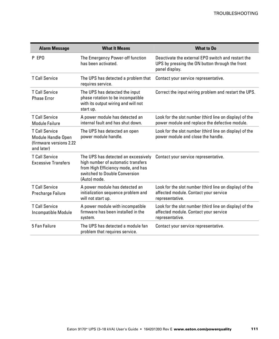
Alarm Message What It Means What to Do
Critical Alarm Messages
EPO
Non-Critical Alarm Messages
Service and Support
114
Two-Year Limited Warranty US and Canada
Warranty
Warranty
Ferrups
Load Protection Guarantee US and Canada
118

