Removal and Replacement Procedures
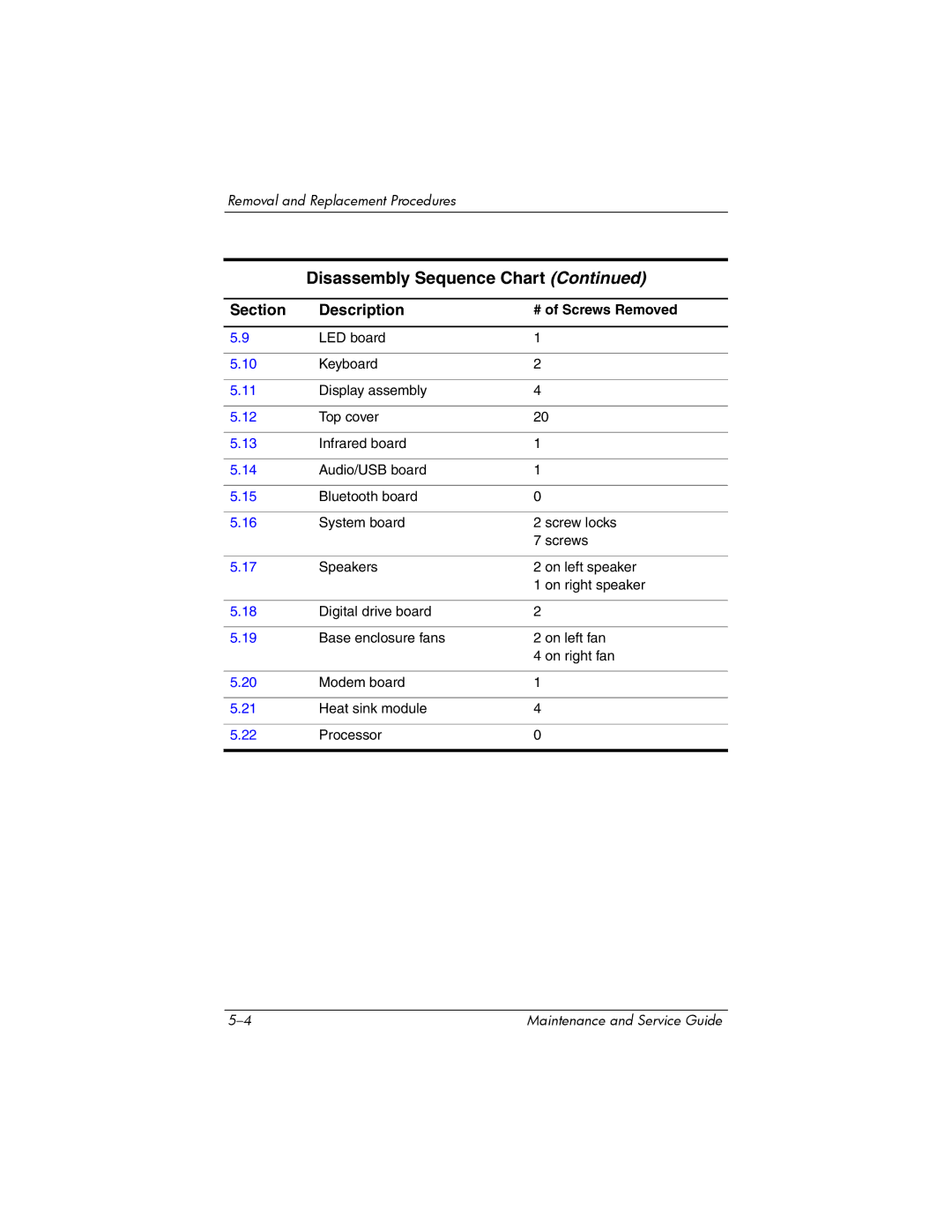
Disassembly Sequence Chart (Continued)
Section | Description | # of Screws Removed |
|
|
|
5.9 | LED board | 1 |
|
|
|
5.10 | Keyboard | 2 |
|
|
|
5.11 | Display assembly | 4 |
|
|
|
5.12 | Top cover | 20 |
|
|
|
5.13 | Infrared board | 1 |
|
|
|
5.14 | Audio/USB board | 1 |
|
|
|
5.15 | Bluetooth board | 0 |
|
|
|
5.16 | System board | 2 screw locks |
|
| 7 screws |
|
|
|
5.17 | Speakers | 2 on left speaker |
|
| 1 on right speaker |
|
|
|
5.18 | Digital drive board | 2 |
|
|
|
5.19 | Base enclosure fans | 2 on left fan |
|
| 4 on right fan |
|
|
|
5.20 | Modem board | 1 |
|
|
|
5.21 | Heat sink module | 4 |
|
|
|
5.22 | Processor | 0 |
|
|
|
Maintenance and Service Guide |