Maintenance and Service Guide
Page
Contents
Removal and Replacement Procedures
Product Description
Features
Product Description
Power Management
Resetting the Notebook
Front Components
External Components
Right-Side Components
Right-Side Components
Left-Side Components
Rear Panel Components
Standard Keyboard Components
Caps lock key
Standard Keyboard Components
Upper Keyboard Components
Upper Keyboard Components
Product Description
On num lock or the numeric keypad is on
Bottom Components
Bottom Components
Design Overview
Computer Setup
Troubleshooting
Select To Do This
Main Menu
Security Menu
Selecting from the Security Menu
Advanced Menu
Selecting from the Advanced Menu
Troubleshooting Flowcharts Overview
Troubleshooting Flowcharts
Flowchart 2.14-No OS Loading, Optical Drive
Flowchart No Power Part
Flowchart 2.1-Initial Troubleshooting
Flowchart 2.2-No Power, Part
Flowchart 2.3-No Power, Part
External
Flowchart 2.4-No Power, Part
Flowchart 2.5-No Power, Part
Flowchart 2.6-No Video, Part
Flowchart No Video Part
Flowchart 2.7-No Video, Part
Nonfunctioning expansion base
Flowchart 2.8-Nonfunctioning Expansion Base if applicable
Go to Flowchart 2.13-No OS Loading Diskette Drive
Flowchart 2.9-No Operating System OS Loading
Loading
Flowchart 2.10-No OS Loading, Hard Drive, Part
Flowchart No OS Loading Hard Drive, Part
Flowchart 2.11-No OS Loading, Hard Drive, Part
Can bad sectors be fixed?
Flowchart 2.12-No OS Loading, Hard Drive, Part
Utility?
Flowchart 2.13-No OS Loading, Diskette Drive
Flowchart 2.14-No OS Loading, Optical Drive
Flowchart 2.15-No Audio, Part
Flowchart 2.16-No Audio, Part
Cmos
Flowchart 2.17-Nonfunctioning Device
Flowchart 2.18-Nonfunctioning Keyboard
Pointing device Not operating Properly Connect notebook
Flowchart 2.19-Nonfunctioning Pointing Device
Flowchart 2.20-No Network/Modem Connection
Serial Number Location
Illustrated Parts Catalog
Illustrated Parts Catalog
Keyboards
Switch cover
Broadcomm Bluetooth wireless board
Spare Parts Notebook Major Components
Illustrated Parts Catalog
Base enclosure right fan
Audio/USB board includes cable
Modem board
Base enclosure middle fan
Illustrated Parts Catalog
USB digital drive board
Battery pack, 12-cell, 2.2-AHr
Mini PCI communications cards
Memory modules 400-MHz DDR2
Spare Part
Miscellaneous Plastics Kit
Spare Part Number
Optical drives
Mass Storage Devices
Spare Part Number Information
Media Center Edition Accessories
Spare Part Information
Miscellaneous Not Illustrated
Description Number
Spare Part Information
Spare Part Information
Sequential Part Number Listing
Sequential Part Number Listing
Sequential Part Number Listing
Sequential Part Number Listing
Sequential Part Number Listing
Sequential Part Number Listing
Sequential Part Number Listing
Sequential Part Number Listing
Tools Required
Removal and Replacement Preliminaries
Plastic Parts
Service Considerations
Preventing Damage to Removable Drives
Preventing Electrostatic Damage
Packaging and Transporting Precautions
Use the following grounding precautions at workstations
Workstation Precautions
Grounding Equipment and Methods
Material Use Voltage Protection Level
Typical Electrostatic Voltage Levels
Static-Shielding Materials
Relative Humidity Event 10% 40% 55%
Removal and Replacement Procedures
Serial Number
# of Screws Removed
Disassembly Sequence Chart
Disassembly Sequence Chart
Disassembly Sequence Chart
Battery Pack Spare Part Number Information
Preparing the Notebook for Disassembly
Reverse the above procedure to install the battery pack
Removing the Hard Drive Cover
Hard Drive Spare Part Number Information
Removing the Hard Drive
Removing the Hard Drive Frame and Connector
Replacing the Notebook Feet
Optical Drive
Reverse the above procedure to install an optical drive
Memory Module
Reverse the above procedure to install a memory module
Mini PCI Communications Card
Removing a Mini PCI Communications Card
Switch Cover
Reverse the above procedure to install the switch cover
LED Board
Reverse the above procedure to install the LED board
Keyboard
Removing the Keyboard Screws
Releasing the Keyboard
Reverse the above procedure to install the keyboard
Display Assembly
Disconnecting the Display Cables
Removing the Display Screws
Reverse the above procedure to install the display assembly
Top Cover
Removing the Top Cover Screws, Part
Disconnecting the TouchPad and LED Board Cables
Reverse the above procedure to install the top cover
Infrared Board
Reverse the above procedure to install the infrared board
Audio/USB Board
Reverse the above procedure to install the audio/USB board
Bluetooth Board
Reverse the above procedure to install the Bluetooth board
System Board
Disconnecting the Fan Cables
Disconnect the fan cable from the system board
Removing the System Board Screws and Screw Locks
Removing the System Board
Speakers
Removing the Left Speaker
Reverse the above procedure to install the speakers
USB Digital Drive Board
Removing the Digital Drive Board
Base Enclosure Fans
Removing the Base Enclosure Fans
Modem Board
Reverse the above procedure to install the modem board
Heat Sink Module
Reverse the above procedure to install the heat sink module
Processor
Disengaging the Processor Release Arm
Reverse the above procedure to install the processor
Temperature
Dimensions
Weight
Stand-alone power requirements
Random Vibration
Maximum altitude unpressurized
Shock
Inch, WSXGA+WVA Brightview Display
Inch, WXGA+WVA Brightview Display
Hard Drives, Part
Disk rotational speed
60-GB 40-GB Dimensions
Energy
Primary 12-cell, Li-Ion Battery Pack
Disk diameter
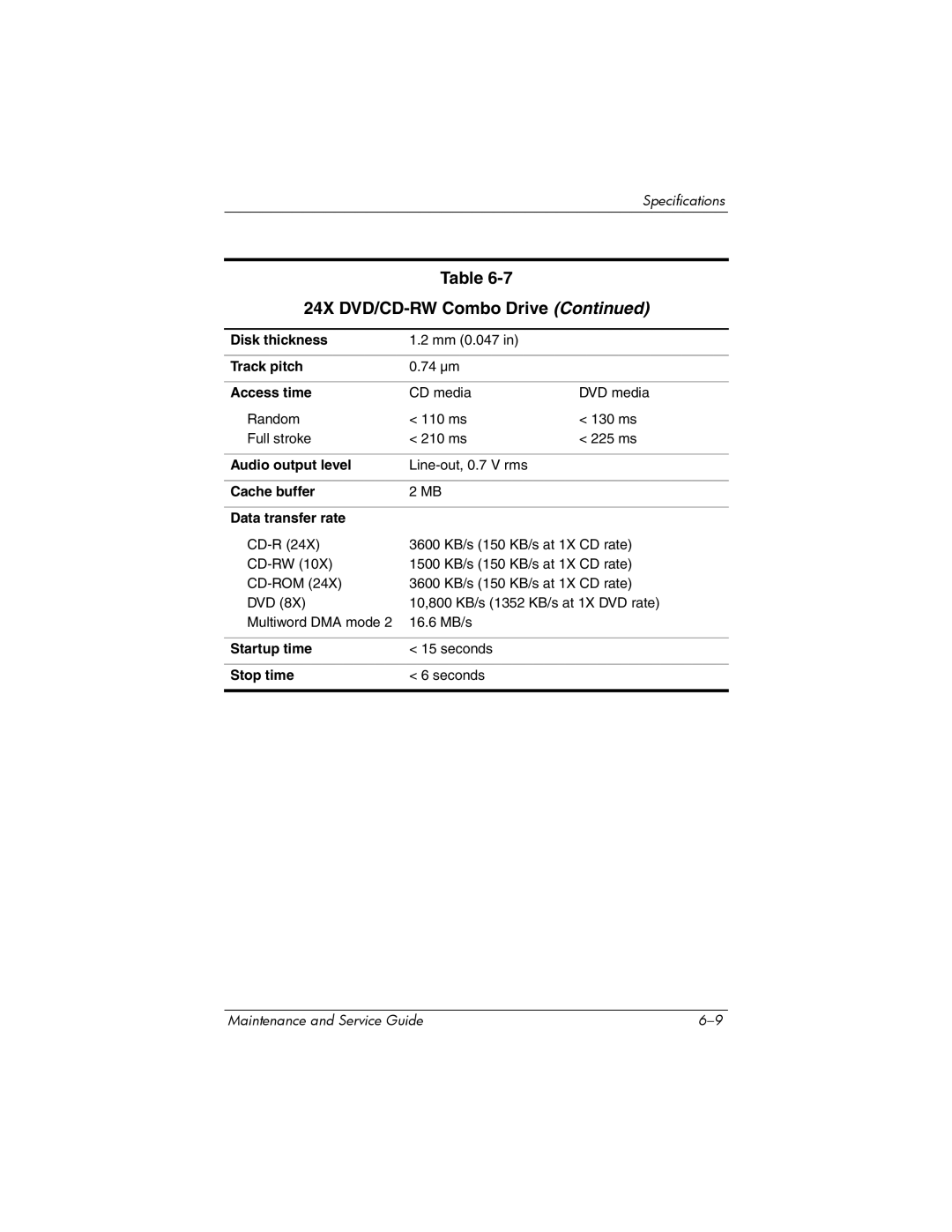
24X DVD/CD-RW Combo Drive
Applicable disk Read Write
Center hole diameter
Audio output level
Access time
Disk thickness
Track pitch
8X DVD±RW/R and CD-RW Combo Drive
DVD
Hardware DMA System Function
System DMA
Hardware IRQ System Function
System Interrupts
IRQ12
Address hex
System I/O Addresses
16F Unused
VGA
Size Memory Address System Function
System Memory Map
Table A-1 Universal Serial Bus
Pin Signal
Table A-3 Video-Out
Table A-2 RJ-45 Network
Table A-4 External Monitor
Table A-5 RJ-11 Modem
Table A-6 Audio-In Microphone
Table A-7 Audio-Out Headphone
Conductor Power Cord Set
Power Cord Set Requirements
General Requirements
Country Accredited Agency Applicable Note Number
Conductor Power Cord Set Requirements
Country-Specific Requirements
BSI
Screw Listing
Head
Color Qty Length Thread Width Black Where used
Table C-1 Phillips PM2.0×5.0 Screw
Table C-2 Phillips PM2.5×4.0 Screw
Color Qty Length Thread Width Silver Where used
Table C-3 Phillips PM2.0×8.0 Screw
Phillips M2.0×8.0 Screw Locations
Table C-3 Phillips PM2.0×8.0 Screw
Table C-3 Phillips PM2.0×8.0 Screw
Table C-3 Phillips PM2.0×8.0 Screw
Phillips M2.0×8.0 Screw Location
Table C-3 Phillips PM2.0×8.0 Screw
Table C-4 Phillips PM2.0×3.0 Screw
Phillips M2.0×3.0 Screw Location
Table C-5 Phillips PM2.0×6.0 Screw
Head Color Qty. Length Thread Width
Table C-6 Hex Socket HM5.0×9.0 Screw Lock
Table C-7 Phillips PM2.0×4.0 Screw
Table C-7 Phillips PM2.0×4.0 Screw
Phillips M2.0×3.0 Screw Location
Table C-7 Phillips PM2.0×4.0 Screw
Table C-8 Phillips PM1.5×3.5 Screw
Table C-9 Phillips PM2.0×12.0 Spring-Loaded Shoulder Screw
Color Qty Length Thread Width Silver 12.0 mm Where used
Index
Index
Index-3
Index-4
Num lock key 1-11 num lock light
Index-6
Index-7