UPS WITH BYPASS ELECTRICAL INSTALLATION
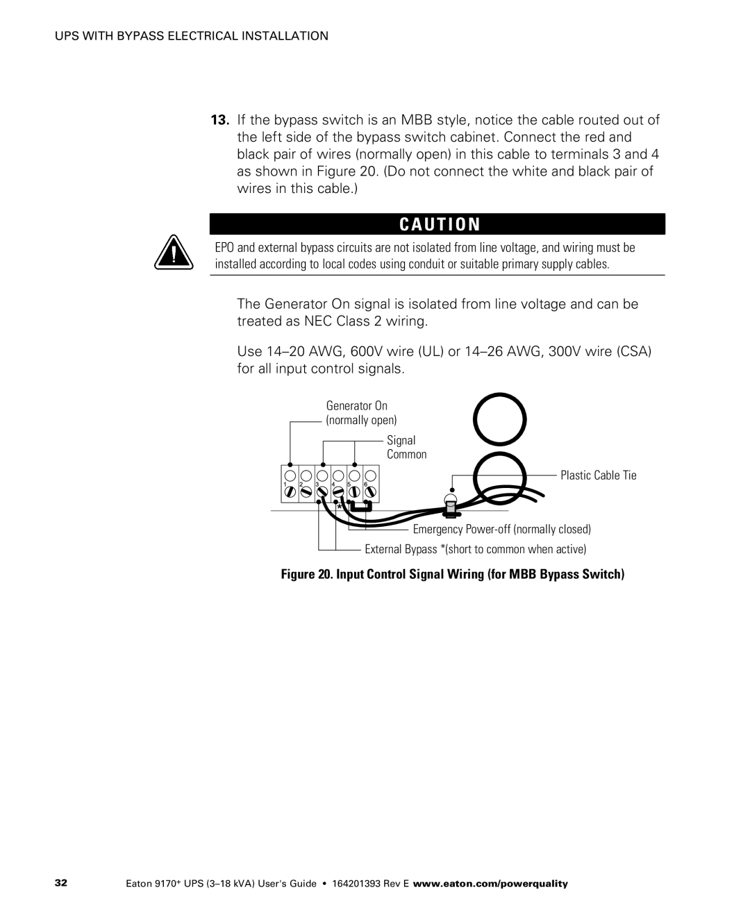
13.If the bypass switch is an MBB style, notice the cable routed out of the left side of the bypass switch cabinet. Connect the red and black pair of wires (normally open) in this cable to terminals 3 and 4 as shown in Figure 20. (Do not connect the white and black pair of wires in this cable.)
C A U T I O N
EPO and external bypass circuits are not isolated from line voltage, and wiring must be installed according to local codes using conduit or suitable primary supply cables.
The Generator On signal is isolated from line voltage and can be treated as NEC Class 2 wiring.
Use
Generator On (normally open)
Signal
Common
Plastic Cable Tie
Emergency |
External Bypass *(short to common when active)
Figure 20. Input Control Signal Wiring (for MBB Bypass Switch)
32 | Eaton 9170+ UPS |