Installation of Optional Modules

Installation

2.6.2 4XTMF, 4XLMF and 4XZMF Option Modules

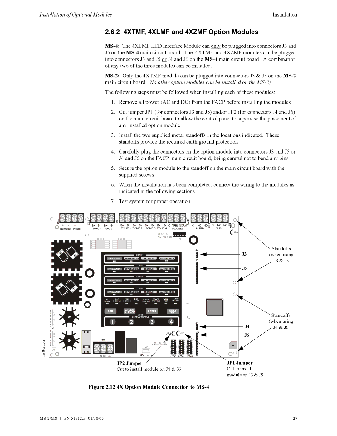
MS-4:The 4XLMF LED Interface Module can only be plugged into connectors J3 and J5 on the MS-4main circuit board. The 4XTMF and 4XZMF modules can be plugged into connectors J3 and J5 or J4 and J6 on the MS-4main circuit board. A combination of any two of the three modules can be installed.

MS-2:Only the 4XTMF module can be plugged into connectors J3 & J5 on the MS-2main circuit board. (No other option modules can be installed on the MS-2).

The following steps must be followed when installing each of these modules:

1.Remove all power (AC and DC) from the FACP before installing the modules

2.Cut jumper JP1 (for connectors J3 and J5) and/or JP2 (for connectors J4 and J6) on the main circuit board to allow the control panel to supervise the placement of any installed option module

3.Install the two supplied metal standoffs in the locations indicated. These standoffs provide the required earth ground protection

4.Carefully plug the connectors on the option module into connectors J3 and J5 or J4 and J6 on the FACP main circuit board, being careful not to bend any pins

5.Secure the option module to the standoff on the main circuit board with the supplied screws

6.When the installation has been completed, connect the wiring to the modules as indicated in the following sections

7.Test system for proper operation

TB1

+

-

+

-

TB2

B+ B-

B+

B-

TB3

B+

B-

B+

B-

B+

B-

B+

B-

C TRBL NORM

C

NC NOTB6

C

NC

NO


TB5


Nonreset

Reset


NAC 1

NAC 2


ZONE 1 ZONE 2

ZONE 3 ZONE 4

TROUBLE


ALARM


SUPV


CLASS A


CONVERTER


J1


J3


ZONE 1


FIRE ALARM

SUPERVISORY

TROUBLE

MAINTENANCE

J5


ZONE 2


FIRE ALARM

SUPERVISORY

TROUBLE

MAINTENANCE


ZONE 3


FIRE ALARM

SUPERVISORY

TROUBLE

MAINTENANCE


ZONE 4


FIRE ALARM

SUPERVISORY

TROUBLE

MAINTENANCE

AC

NAC

ZONE

NAC

SYSTEM

POWER

WALK

ALARM

POWER

DISABLE

DISABLE

FAULT

TROUBLE

TROUBLE TEST

SILENCE

TB7

JP3

Standoffs

J3 (when using

J3 & J5

J5

ms4bord.cdr

TRANSFORMER 2 TRANSFORMER 1

J9

J7

ACK

ALARM

RESET

WALK


SILENCE

ZONE

TEST


1

ENABLE/DISABLE

4


2

3


J4


JP2

JP1

J6


TB8


1 2

ON

1 2

ON

1 2

ON


EARTH

CHG

3


3


3


J8


4 5


4 5


4 5


6


6


6


7


7


7


BATTERY


8


8


8


HOT NEUT EARTH


SW1 SW2

SW3


Standoffs

(when using

J4 J4 & J6

J6

JP2 Jumper

JP1 Jumper

Cut to install module on J4 & J6

Cut to install


module on J3 & J5

Figure 2.12 4X Option Module Connection to MS-4

MS-2/MS-4 PN 51512:E 01/18/05

27

Page 27
Image 27
Honeywell MS-2 manual 2 4XTMF, 4XLMF and 4XZMF Option Modules, 12 4X Option Module Connection to MS-4

MS-2 specifications

The Honeywell MS-2 is a sophisticated control panel designed for fire alarm detection systems. It is renowned for its reliability, efficiency, and advanced features which make it a popular choice among industry professionals. The MS-2 is especially well-suited for small to medium-sized commercial buildings, providing comprehensive fire detection and alarm capabilities.

One of the standout features of the Honeywell MS-2 is its dual-loop architecture. This allows for the connection of two loop circuits, each capable of supporting a wide range of devices such as smoke detectors, heat detectors, and manual pull stations. This flexibility in device connectivity enables tailored solutions based on specific building requirements, ensuring maximum safety and compliance with fire codes.

The MS-2 incorporates a user-friendly graphical interface that simplifies operation and monitoring. This LCD display provides real-time system status updates, which allows users to quickly identify any issues or alarms. Moreover, it features intuitive navigation buttons, making it easy for operators to interact with system functionalities.

In terms of technology, the MS-2 is built upon a robust digital platform that ensures precise detection and response times. With advanced signal processing capabilities, the system can differentiate between actual fire signals and nuisance alarms, thereby minimizing false alarms. This not only enhances safety but also reduces unnecessary disruptions and maintenance costs.

The MS-2 also supports addressable technology, enabling precise identification of device locations within the system. This is particularly beneficial in emergency situations where rapid response is critical. Furthermore, the panel can facilitate remote monitoring, allowing for real-time data access and integration with building management systems, thereby enhancing overall operational efficiency.

Another noteworthy characteristic of the Honeywell MS-2 is its compliance with various industry standards, ensuring that it meets the stringent requirements of fire safety regulations. The system is compatible with a wide range of Honeywell's fire alarm devices, offering versatility and scalability for future expansions.

In conclusion, the Honeywell MS-2 fire alarm control panel combines advanced technology, user-friendly design, and robust features to deliver reliable fire safety solutions. Its dual-loop capability, addressable technology, and real-time monitoring make it an ideal choice for businesses aiming to enhance their fire safety infrastructure. By choosing the MS-2, organizations can better protect their assets, ensure compliance, and safeguard the lives of occupants.