Honeywell MS-2 Strobe Synchronization, Maximum Number of Strobes for Synchronization, Spares

Models: MS-2

1 56
Download 56 pages 46.39 Kb
Page 37
Image 37

DIP Switch Settings

Program Options via DIP Switch

3.1.3.5 Strobe Synchronization

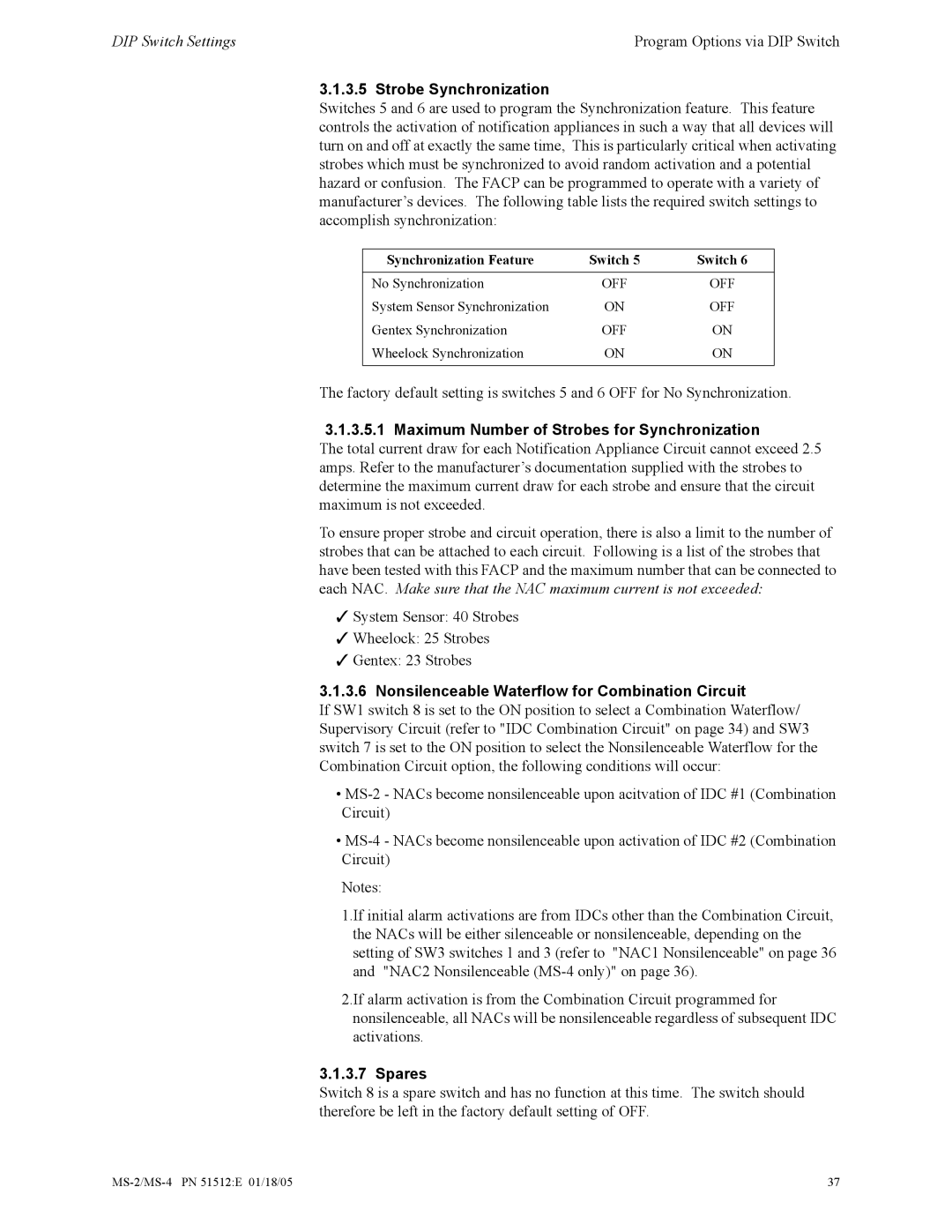
Switches 5 and 6 are used to program the Synchronization feature. This feature controls the activation of notification appliances in such a way that all devices will turn on and off at exactly the same time, This is particularly critical when activating strobes which must be synchronized to avoid random activation and a potential hazard or confusion. The FACP can be programmed to operate with a variety of manufacturer’s devices. The following table lists the required switch settings to accomplish synchronization:

Synchronization Feature

Switch 5

Switch 6


No Synchronization

OFF

OFF

System Sensor Synchronization

ON

OFF

Gentex Synchronization

OFF

ON

Wheelock Synchronization

ON

ON


The factory default setting is switches 5 and 6 OFF for No Synchronization.

3.1.3.5.1 Maximum Number of Strobes for Synchronization

The total current draw for each Notification Appliance Circuit cannot exceed 2.5 amps. Refer to the manufacturer’s documentation supplied with the strobes to determine the maximum current draw for each strobe and ensure that the circuit maximum is not exceeded.

To ensure proper strobe and circuit operation, there is also a limit to the number of strobes that can be attached to each circuit. Following is a list of the strobes that have been tested with this FACP and the maximum number that can be connected to each NAC. Make sure that the NAC maximum current is not exceeded:

System Sensor: 40 Strobes

Wheelock: 25 Strobes

Gentex: 23 Strobes

3.1.3.6 Nonsilenceable Waterflow for Combination Circuit

If SW1 switch 8 is set to the ON position to select a Combination Waterflow/ Supervisory Circuit (refer to "IDC Combination Circuit" on page 34) and SW3 switch 7 is set to the ON position to select the Nonsilenceable Waterflow for the Combination Circuit option, the following conditions will occur:

MS-2 - NACs become nonsilenceable upon acitvation of IDC #1 (Combination Circuit)

MS-4 - NACs become nonsilenceable upon activation of IDC #2 (Combination Circuit)

Notes:

1.If initial alarm activations are from IDCs other than the Combination Circuit, the NACs will be either silenceable or nonsilenceable, depending on the setting of SW3 switches 1 and 3 (refer to "NAC1 Nonsilenceable" on page 36 and "NAC2 Nonsilenceable (MS-4 only)" on page 36).

2.If alarm activation is from the Combination Circuit programmed for nonsilenceable, all NACs will be nonsilenceable regardless of subsequent IDC activations.

3.1.3.7 Spares

Switch 8 is a spare switch and has no function at this time. The switch should therefore be left in the factory default setting of OFF.

MS-2/MS-4 PN 51512:E 01/18/05

37

Page 37
Image 37
Honeywell MS-2 manual Strobe Synchronization, Maximum Number of Strobes for Synchronization, Spares

MS-2 specifications

The Honeywell MS-2 is a sophisticated control panel designed for fire alarm detection systems. It is renowned for its reliability, efficiency, and advanced features which make it a popular choice among industry professionals. The MS-2 is especially well-suited for small to medium-sized commercial buildings, providing comprehensive fire detection and alarm capabilities.

One of the standout features of the Honeywell MS-2 is its dual-loop architecture. This allows for the connection of two loop circuits, each capable of supporting a wide range of devices such as smoke detectors, heat detectors, and manual pull stations. This flexibility in device connectivity enables tailored solutions based on specific building requirements, ensuring maximum safety and compliance with fire codes.

The MS-2 incorporates a user-friendly graphical interface that simplifies operation and monitoring. This LCD display provides real-time system status updates, which allows users to quickly identify any issues or alarms. Moreover, it features intuitive navigation buttons, making it easy for operators to interact with system functionalities.

In terms of technology, the MS-2 is built upon a robust digital platform that ensures precise detection and response times. With advanced signal processing capabilities, the system can differentiate between actual fire signals and nuisance alarms, thereby minimizing false alarms. This not only enhances safety but also reduces unnecessary disruptions and maintenance costs.

The MS-2 also supports addressable technology, enabling precise identification of device locations within the system. This is particularly beneficial in emergency situations where rapid response is critical. Furthermore, the panel can facilitate remote monitoring, allowing for real-time data access and integration with building management systems, thereby enhancing overall operational efficiency.

Another noteworthy characteristic of the Honeywell MS-2 is its compliance with various industry standards, ensuring that it meets the stringent requirements of fire safety regulations. The system is compatible with a wide range of Honeywell's fire alarm devices, offering versatility and scalability for future expansions.

In conclusion, the Honeywell MS-2 fire alarm control panel combines advanced technology, user-friendly design, and robust features to deliver reliable fire safety solutions. Its dual-loop capability, addressable technology, and real-time monitoring make it an ideal choice for businesses aiming to enhance their fire safety infrastructure. By choosing the MS-2, organizations can better protect their assets, ensure compliance, and safeguard the lives of occupants.