CONNECTING TO THE MFM
BACK CONNECTIONS
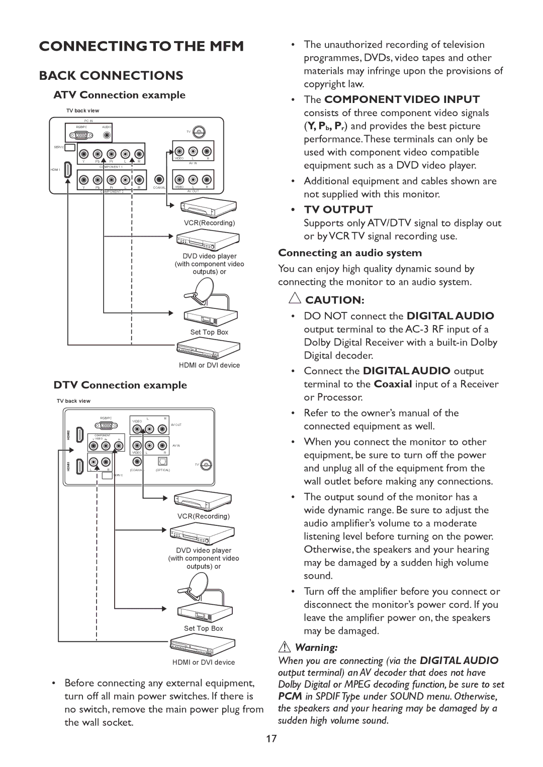
ATV Connection example
• | The unauthorized recording of television |
| programmes, DVDs, video tapes and other |
| materials may infringe upon the provisions of |
| copyright law. |
• | The COMPONENT VIDEO INPUT |
TV back view
PC IN
|
|
| RGB/PC |
|
| AUDIO |
|
|
| ||
|
|
|
|
|
|
|
|
|
|
|
|
|
|
|
|
|
|
|
|
|
|
|
|
|
|
|
|
|
|
|
|
|
|
|
|
|
|
|
|
|
|
|
|
|
|
| |
|
|
|
|
|
|
|
|
| |||
SERV.C |
|
|
|
|
|
|
| ||||
|
|
|
| Y |
| Pb | Pr | L | R | ||
HDMI 1 |
|
|
|
|
|
| COMPONENT 1 |
|
| ||
|
|
|
| Y |
| Pb | Pr | L | R | ||
|
|
|
|
| |||||||
|
|
|
|
|
|
|
| COMPONENT 2 |
|
| |
|
| TV |
|
|
|
|
|
|
|
|
|
| |
| VIDEO | L |
|
| R | |
|
| AV IN |
|
|
| |
|
|
|
|
|
| |
COAXIAL | VIDEO | L |
|
| R | |
AV OUT
VCR(Recording)
DVD video player
(with component video
outputs) or
consists of three component video signals |
(Y, Pb, Pr) and provides the best picture |
performance.These terminals can only be |
used with component video compatible |
equipment such as a DVD video player. |
• Additional equipment and cables shown are |
not supplied with this monitor. |
• TV OUTPUT |
Supports only ATV/DTV signal to display out |
or by VCR TV signal recording use. |
Connecting an audio system
You can enjoy high quality dynamic sound by connecting the monitor to an audio system.
![]() CAUTION:
CAUTION:
Set Top Box
HDMI or DVI device
DTV Connection example
TV back view
|
|
|
| RGB/PC |
|
| VIDEO | L | R |
| ||
HDMI2 |
|
|
|
|
|
|
|
|
|
|
| AV OUT |
|
|
|
|
|
|
|
|
| ||||
|
|
| Y VIDEO Pb | Pr |
|
|
|
|
| |||
|
|
|
| COMPONENT |
|
|
|
|
|
| ||
|
|
|
|
|
|
|
|
| ||||
AV IN
|
|
| VIDEO | L | R |
HDMI1 |
|
|
|
| TV |
L | R | (COAXIAL) |
| (OPTICAL) | |
|
|
| SERV.C |
|
|
|
|
|
|
| VCR(Recording) |
|
|
|
|
| DVD video player |
|
|
|
|
| (with component video |
|
|
|
|
| outputs) or |
|
|
|
|
| Set Top Box |
HDMI or DVI device
•Before connecting any external equipment, turn off all main power switches. If there is no switch, remove the main power plug from
the wall socket.
•DO NOT connect the DIGITAL AUDIO output terminal to the
•Connect the DIGITAL AUDIO output terminal to the Coaxial input of a Receiver or Processor.
•Refer to the owner’s manual of the connected equipment as well.
•When you connect the monitor to other equipment, be sure to turn off the power and unplug all of the equipment from the wall outlet before making any connections.
•The output sound of the monitor has a wide dynamic range. Be sure to adjust the audio amplifier’s volume to a moderate listening level before turning on the power. Otherwise, the speakers and your hearing may be damaged by a sudden high volume sound.
•Turn off the amplifier before you connect or disconnect the monitor’s power cord. If you leave the amplifier power on, the speakers may be damaged.
![]() Warning:
Warning:
When you are connecting (via the DIGITAL AUDIO output terminal) an AV decoder that does not have Dolby Digital or MPEG decoding function, be sure to set PCM in SPDIF Type under SOUND menu. Otherwise, the speakers and your hearing may be damaged by a sudden high volume sound.
17