Manuals
/
HP
/
Computer Equipment
/
Laptop
HP
2730p 2730p
manual
Computer major components
Models:
2730p 2730p
1
24
121
121
Download
121 pages
35.82 Kb
21
22
23
24
25
26
27
28
Specification
Bluetooth
Pin Signal
Password
Wireless antenna locations
Maintenance
System Configuration menu
Computer Setup
Audio connector board
Display assembly
Page 24
Image 24
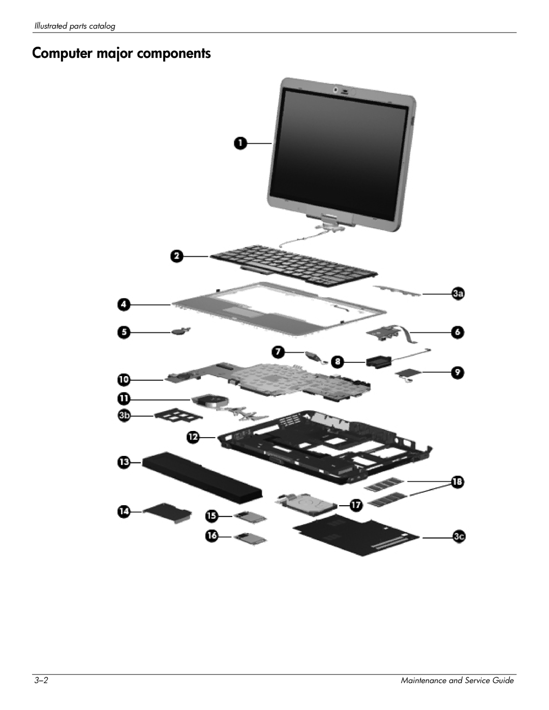
Illustrated parts catalog
Computer major components
3–2
Maintenance and Service Guide
Page 23
Page 25
Page 24
Image 24
Page 23
Page 25
Contents
Maintenance and Service Guide
HP EliteBook 2730p Notebook PC
Page
Safety warning notice
Contents
Computer Setup
11Recycling
Product description
Chipset
Graphics
Panel
Wireless Integrated Wlan options by way of wireless module
Category Description Mass storage drives
Optical drives
Diskette drive
Power requirements
Operating system Preinstalled without Microsoft Office
Preinstalled with Microsoft Office
Category Description Docking
Category Description Operating system Restore media
Serviceability End-user replaceable parts
Web support
Wireless antenna locations
External component identification
Top components
Component Description
Display components
Buttons and switches
Keys
Component Description Esc key
Fn key
Lights
Pointing devices
Hardware and Sound Mouse
System and Maintenance Power Options
Front components
Right-side components
Item Component Description
Left-side components
Connection
Rear components
Bottom components
Illustrated parts catalog
Serial number location
Computer major components
Item Description
Audio connector board includes cable
Bluetooth module
Cell, 4.4-Wh battery
Description Spare Part Number Plastics Kit , includes
Description Spare Part Number Wlan module
Hard drive connector cable not illustrated
Description Spare Part Number
Hspda EV-DO Wwan module
Cable Kit
Mass storage devices
Item Description Spare part number
Plastics Kit
Item Description Spare part number Plastics Kit
Power cords
Miscellaneous parts
Description Spare part number AC adapter
Screw Kit
Sequential part number listing
Spare part number Description
Spare part number Description
Spare part number Description
Antenna transceivers and cables
Removal and replacement procedures
Preliminary replacement requirements
Service considerations
Tools required
Grounding guidelines
Drive handling
Packaging and transporting guidelines
Workstation guidelines
Unknown user password
Material Use Voltage protection level
Component replacement procedures
Serial number location
Computer feet
Battery
SIM
Hard drive
Remove the hard drive bracket
Wlan module
Description Spare part number
Remove the two Phillips PM2.5×4.0 screws
Wwan module
Memory module
Keyboard
Removal and replacement procedures
Removal and replacement procedures
Hinge cover
Top cover
Removal and replacement procedures
RTC battery
Audio connector board
Bluetooth module
Description Spare part number Bluetooth module 483113-001
Speaker
Description Spare part number Speaker 507057-001
Display assembly
Disconnect the display converter cable From the system board
Lift the display assembly straight up and remove it
System board
Removal and replacement procedures
Removal and replacement procedures
Removal and replacement procedures
Fan/heat sink assembly
Turn the system board upside down with the front toward you
Modem module
Modem module spare part kit includes a modem module cable
Computer Setup
Starting Computer Setup
Using Computer Setup
Navigating and selecting in Computer Setup
Computer Setup menus
Restoring factory settings in Computer Setup
File menu
Select To do this
Security menu
Diagnostics menu
System Configuration menu
Options are available
Computer Setup
Select To do this
Specifications
Computer specifications
Inch, Wxga display specifications
Hard drive specifications
System DMA specifications
System interrupt specifications
Hardware DMA System function
Hardware IRQ System function
System I/O address specifications
Address hex System function shipping configuration
EF80-EF9F
System memory map specifications
Size Memory address System function
Screw listing
Phillips PM2.0×5.0 captive screw
Color Quantity Length Thread Head diameter Black
Phillips PM2.0×3.0 screw
Color Quantity Length Thread Head diameter Silver
Where used
Phillips PM2.0×4.0 screw
Torx T8M2.0×8.0 screw
Torx T8M2.0×5.0 screw
Phillips PM2.0×5.0 screw
Screw listing
Phillips PM2.0×4.0 screw
Torx T8M2.5×6.0 screw
Phillips PM2.5×7.0 captive screw
Backup and recovery
Backup and recovery in Windows Vista
Overview
Backing up your information
Performing a recovery
Using the Windows recovery tools
Select Repair your computer
Backup and recovery in Windows XP
Recovering your information
Connector pin assignments
Pin Signal
1394
Audio-in microphone
Audio-out headphone
External monitor
RJ-11 modem
RJ-45 network
Universal Serial Bus
Power cord set requirements
Requirements for all countries and regions
Requirements for specific countries and regions
Country/region Accredited agency Applicable note number
Battery
Recycling
Display
Recycling
Maintenance and Service Guide 11-3
Remove the display panel frame from the display panel
Maintenance and Service Guide 11-5
Disconnect the display cable from the LCD panel
Index
F4 Hard Disk Test 5-5fan/heat sink assembly removal
Maintenance and Service Guide Index-3
Index-4
Maintenance and Service Guide Index-5
Top
Page
Image
Contents