| Removal and replacement procedures |
|
|
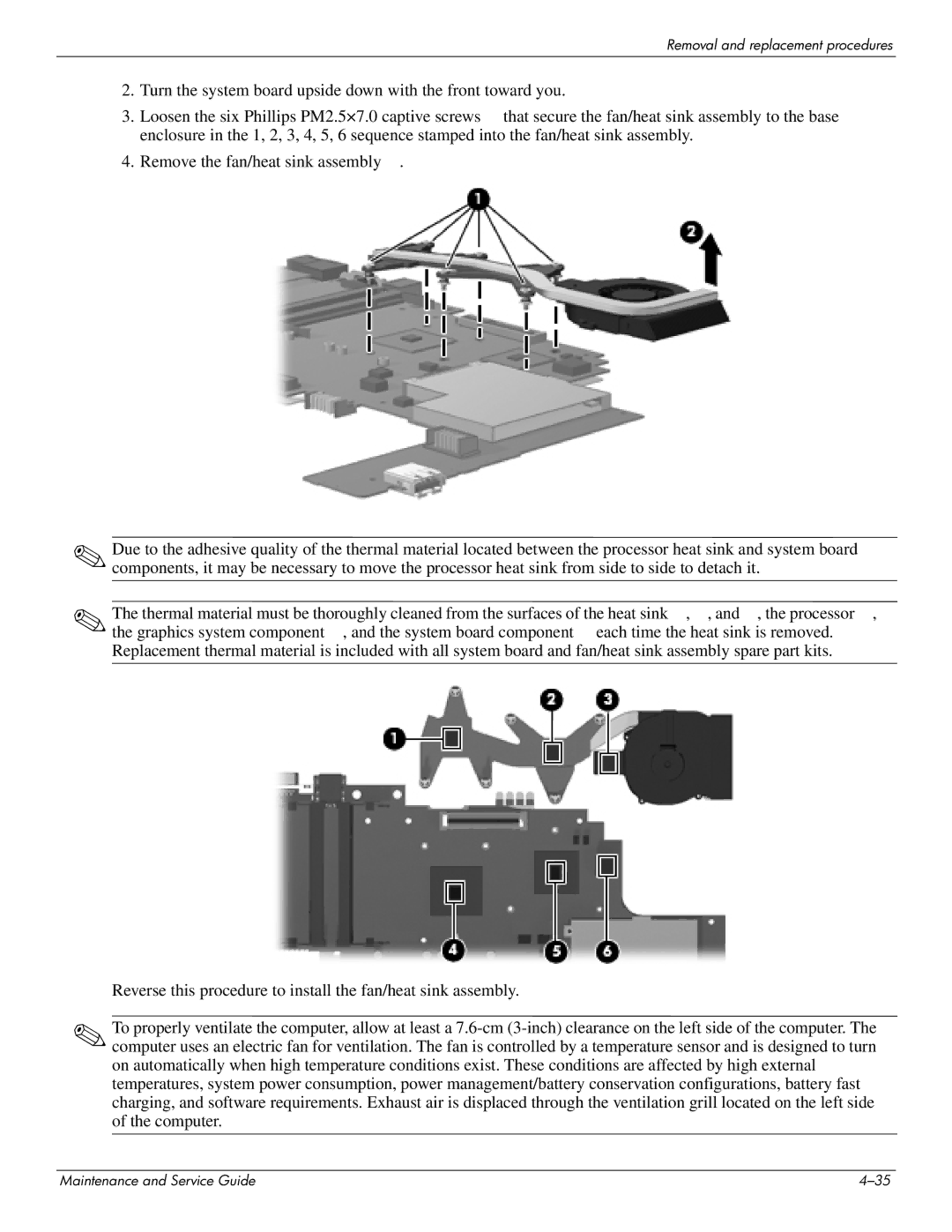
2. | Turn the system board upside down with the front toward you. |
3. | Loosen the six Phillips PM2.5×7.0 captive screws that secure the fan/heat sink assembly to the base |
| enclosure in the 1, 2, 3, 4, 5, 6 sequence stamped into the fan/heat sink assembly. |
4. | Remove the fan/heat sink assembly . |
✎Due to the adhesive quality of the thermal material located between the processor heat sink and system board components, it may be necessary to move the processor heat sink from side to side to detach it.
✎The thermal material must be thoroughly cleaned from the surfaces of the heat sink , , and , the processor , the graphics system component , and the system board component each time the heat sink is removed. Replacement thermal material is included with all system board and fan/heat sink assembly spare part kits.
Reverse this procedure to install the fan/heat sink assembly.
✎To properly ventilate the computer, allow at least a
Maintenance and Service Guide |