Series Series
HP AdvanceStack Routers
Installation Guide
Installation Guide
Hewlett-Packard Series 200 Routers Hewlett-Packard Series 400 Routers
Installation Guide
Preface
Preface
Installation Guide
2. Features and General Hardware Operation
Contents
1. Installation and Initial Setup
Contents
Interpreting ERROR Messages on the HP AdvanceStack
3. Troubleshooting
A. Cables and Connectors
D. FDDI Cable Attachment Configurations
B. Modem Configuration
C. Specifications
Safety Information Regulatory Statements and Warranty Index
Installation and Initial Setup
4. Initializing and verifying the router page
Installation
2. Preparing the network page 3. Preparing the router hardware page
C a u t i o n
Phase 1 Ensure that You Have a Complete Set of Accessories
Phase 1 Ensure that You Have a Complete Set of Accessories
Phase 2 Prepare the Network
Phase 2 Prepare the Network
N o t e
C o n s o l e N o t e
Phase 3 Prepare the Router Hardware
Phase 3 Prepare the Router Hardware
A. Mount the Router
Figure 1-3. Flat On Wall
Single-Height Models
Figure 1-1. Rack Mount - Bracket Position
Figure 1-4. Straight Out From Wall
Figure 1-7. Flat On Wall
Double-Height Models
Figure 1-5. Rack Mount - Bracket Position
Figure 1-6. Rack Mount - Back Out
To install a console
B. Connect a Console Optional
When Is a Console Necessary?
C. Attach Network Cables
C a u t i o n N o t e
Connecting a LAN to the AUI Interface
Figure 1-9. LAN AUI Connection
Figure 1-10. Installing the AUI Retainer
4. Connect the network cable to the transceiver
properly grounded. Refer to ‘‘Safety Information’’ in the back of
Installation
Connecting a LAN to the BNC Interface
W a r n i n g
Figure 1-14. The Installed BNC Connector Cover
Figure 1-12. BNC Connector -- Mid-Cable
other side of the ‘‘T’’ connector
Connecting a LAN to the Token Ring Interface
Connecting an FDDI Ring to the FDDI Interface
MIC A
Figure 1-16. Connecting FDDI Without a Bypass Switch
To port B of adjacent DAS station To port A of adjacent DAS station
MIC B
Figure 1-17. Connecting a Bypass Switch
Using an Optional Bypass Switch to Connect an FDDI Ring
Installation
Disconnect the router from any directly connected FDDI ring
Connecting a WAN to the WAN Interface
Figure 1-18. Connecting a WAN Interface
D. Plug In and Verify the Router Hardware
saved
Self-Test
Power and
Waiting for speed sense
LEDs
Figure 1-21. The Main Menu Screen
Phase 4 Initialize and Verify the Router
Phase 4 Initialize and Verify the Router
This phase involves these steps
Figure 1-24. The Main Menu
A. Create or Modify a Router Configuration
The Shortest Path to a Functioning Configuration
An Overview of Your Configuration Tools
B. Boot the Router
To boot the router now
Figure 1-25. The Default NCL Prompt
Press Y to commence the reboot operation
6. When the copyright screen appears
Figure 1-26. The Copyright Screen
C. Set the Correct Time and Date Optional
time mm/dd/yy hhmmss
D. Set Manager and User Passwords Optional
Setting a Password
Figure 1-27. The NCL Screen with Default Prompt
E. Verify Router Initialization
Figure 1-28. The NCL Selection in the Main Menu
Examine the Event Log
Figure 1-29. The Event Log Line in the Main Menu
Return Advance display by one page P Roll back display by one page
Figure 1-30. Example of the Statistics Screen Menu
1-39
The following service statistics screens are available
Examine the Bridging and Routing Tables
1-42
the Operator’s Reference
Test Node Accessibility
Testing Node Accessibility
Features and General Hardware Operation
Features
Features
Ethernet/802.3 LAN Port with either an AUI-only or AUI/BNC interface
Router Ports
Features
Figure 2-1. Example of AUI and BNC LAN Interfaces
Additional Features
Figure 2-2. Example of Router Front
Interpreting Front-Panel LEDs
Interpreting Front-Panel LEDs
Power
Interpreting Back-Panel LEDs
Reset and Clear
Reset and
Figure 2-7. Example of Port Status LEDs for an FDDI Port
Meanings of Router Status LEDs
Not all port types appear on all routers
Meanings of Port Status LEDs
Router Operation
Net Fail Amber LED The Net Fail LEDs serve two functions
2-10
Figure 2-6. FDDI Thru and Wrap A Operation
FDDI Port
Thru
Optical Bypass - Enabled green
Testing the LEDs
Testing the LEDs
Figure 2-7. Location of the Reset and Clear Buttons
Resetting the Router, Clearing the Passwords, and Clearing the Router
Resetting the Router, Clearing the Passwords, and Clearing the Router
To Reset the Router
To Clear the Manager and User Passwords
To Clear the Router
display the Main menu figure 1-24 on page
Initialization Sequence
Initialization Sequence
Troubleshooting
Introducing Router Troubleshooting Features
Introducing Router Troubleshooting Features
N o t e N o t e
Basic Troubleshooting Tips
Basic Troubleshooting Tips
Table 3-1. LED Error Patterns During Initialization
Interpreting LED Error Patterns
Interpreting LED Error Patterns
Any WAN
Operational fault LED patterns
Any Ports Lit
Interpreting ERROR Messages on the HP AdvanceStack Router 200 Series
Interpreting ERROR Messages on the HP AdvanceStack Router 200 Series
General Procedure for Self-Test Failures
ERROR Incorrect CRC in FLASH ERROR Invalid size field in FLASH
Recoverable Self-Test Failures
ERROR Erasure ERROR, block # ERROR Programming ERROR, block #
ERROR Illegal FLASH ID, byte #, got XXXX, expected YYYY
Non-Recoverable Self-Test Failures
Verifying LED Operation on Other Router Models
Verifying LED Operation
Verifying LED Operation on the HP Router ER, TR, and SR
Verifying LED Operation
Diagnostic Tests
Diagnostic Tests
Testing the Router Only
To test a LAN port 802.3/Ethernet or 802.5/token ring
Testing the Router’s Ports
To test a WAN port
To test an FDDI port
Troubleshooting a Terminal or Modem Connection
Reset Speed Sensing
To test the router’s console port
Adjust Baud Rate
Reset the Terminal
press Return to display the copyright screen or the Main menu screen
Check the Configuration
Test Router’s Console Port
Testing a Transceiver on an Ethernet/802.3 Port
Operator’s Reference
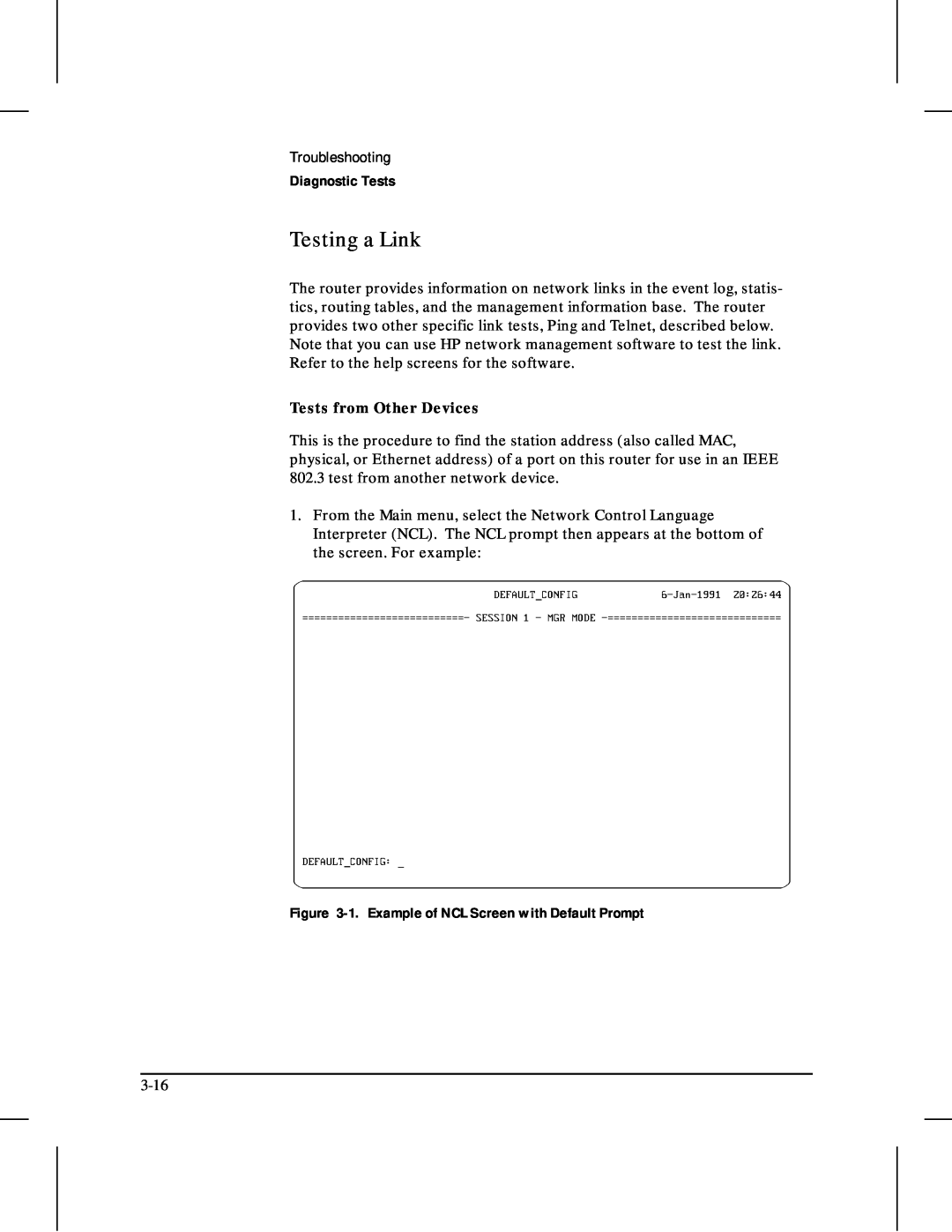
Tests from Other Devices
Testing a Link
Figure 3-1. Example of NCL Screen with Default Prompt
2. At the NCL prompt, enter one of the following commands
Ping
ping ping x.x.x.x count ping x.x.x.x count wait
Telnet
A Cables and Connectors
Cables and Connectors
Cable and Connector on Router
HP Cables
Cables and A Connectors
HP Cables
Other Standard Cables
Other Standard Cables
Standard Cable or Cable Solution
RS-232 Modem Cable-Minimum Pin-Outs
Cable and Connector Pin-Outs
Router Console Port Connector Pin-Outs
Cable and Connector Pin-Outs
25-pin male
Terminal/PC end
Router end
Router End
RS-232 Cable for HP Portable 110 and Portable Plus-Minimum Pin-Outs
Null-Modem Adapter for Use with Modem Cable-Minimum Pin-Outs
Modem Cable End
Data In, Shield common drain
Router AUI LAN Port Definition
AUI Cable-Minimum Pin-Outs
WAN link
RS-449/422 WAN Cable-Minimum Pin-Outs
RS-449 Signal Name
62-pin male
V.35 WAN Cable-Minimum Pin-Outs
A-10
15-pin male
X.21 WAN Cable-Minimum Pin-Out
WAN link end
RS-232 WAN Cable-Minimum Pin-Outs
Description
Back-to-Back Test Cables
Connector at End
For Other Device
A-14
A-15
and RDB and so on, must be twisted pairs of wire
For the pinouts of this cable, turn the page
and RDB, and so on must be twisted pairs of wire
A-16
Pin Definition of Token Ring Connector
Router Token Ring/802.5 LAN Port Definition
Figure A-1. Router Token Ring 802.5 MIC Connector
Connector
A-18
FDDI Optical Bypass DIN Connector Pinouts HP Part Number
Figure A-2. FDDI Bypass Mini DIN Connector Pinouts
FDDI Cable
Figure A-3. Example of FDDI Cable
For an AUI LAN Port
Loopback Connectors
For the Console Port
For a Token Ring/802.5 Port
For an FDDI Port
For a WAN Port
HP part number 28606-63007 pin connections pin 9 to pin pin 10 to pin
B Modem Configuration
HP 50759A Support Link
HP 35031A Support Link
HP 37212B Support Link
Modem Configuration
Configuration
Hayes 2400 Smartmodem
Black Box V.32 9600 Async
Modem
C Specifications
Specifications
Power Consumption
Physical without brackets
Dimensions
Electromagnetic Emissions
Safety Approvals
Environmental
Acoustical for Germany
Cable Interfaces
Data Communications Specifications
Specifications
North AmericaTelenet, Tymnet, Infonet, DDN Europe Austria Belgium
FDDI Cable Attachment Configurations
FDDI Cable Attachment Configurations
Figure D-1. Example of Dual-Attach Station Connections
Dual-Attach Station DAS
Dual-Attach Station DAS
Figure D-2. Example of Single-Attach Station Connections
Single-Attach Station SAS
Single-Attach Station SAS
Figure D-3. Example of Dual-Homed Connection
Dual-Homed Connection
Dual-Homed Connection
Safety Symbols
Safety Information
Safety Information
Safety Information
Informations concernant la sécurité
Informations concernant la sécurité
Symboles de sécurité
AVERTISSEMENT
Hinweise zur Sicherheit
Hinweise zur Sicherheit
Sicherheitssymbole
VORSICHT
Simboli di sicurezza
Considerazioni sulla sicurezza
Considerazioni sulla sicurezza
PERICOLO
Símbolos de seguridad
Consideraciones sobre seguridad
Consideraciones sobre seguridad
Safety Information
and Warranty
Regulatory Statements and Warranty
Regulatory Statements and Warranty
FCC Statement For U.S.A. Only
European Community
VCCI Class 1 Japan Only For the HP Router PR/FR/TFR/LR/BR
Declarations of Conformity
HP Router ER HP Router TR HP Router SR
HP Router PR HP Router FR HP Router TFR HP Router LR HP Router BR
Three-Year Limited Hardware Warranty
Third-Party Products HP designed the HP routers described in this guide to operate with industry-standard hardware and software products
Software or Firmware Warranty
Index
Index
See null modem cable current ...C-2
See data communications specifications concentrator, FDDI ...D-4
Index
G - H
See HP Router ER HP cables ...A-3
See network management manager password See password manuals
See transceiver MIB
See station address
See boot regulatory ...1-2 remote bridge ...A-3, A-13 Remote devices
Q - R
See Telnet
See trunk coupling unit
See specifications
See WAN ports
waiting for speed sense ...3-12 - 3-14 wall mount ...1-7
weight ...C-2
XCVR signal polling ...3-5 XCVR Signal Polling parameter XNS/IPX
WAN ...2-9 cable ...C-4
Copyright 1994 Hewlett-Packard Company Printed in Singapore 7/94
Manual Part Number