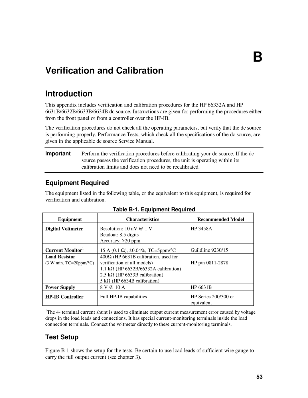
6631B, 6633B, 6634B, 6632B specifications
The HP 6632B, 6634B, 6612B, and 6633B are high-performance programmable power supplies that have gained prominence in various testing and measurement applications. These models are part of the HP 6000 series, which is renowned for its reliability and versatility in providing precision power supply solutions.The HP 6632B offers a dual-output capability, delivering up to 32 volts and 3 amps per channel. It is designed for applications requiring stable and accurate voltage and current supplies. With features like overvoltage protection and short-circuit protection, it ensures the safety of both the device under test and the power supply itself. The programmable voltage and current settings allow operators to automate their testing procedures, increasing efficiency.
The HP 6634B takes performance a step further with multiple outputs, providing up to 32 volts and 5 amps per channel. This model is particularly suited for applications requiring higher current, especially in battery testing and device characterization. The ability to program the device remotely adds an extra layer of usability, making it ideal for integration into automated testing environments.
The HP 6612B model is tailored for users who require a compact and portable power supply solution. It delivers up to 20 volts and 2 amps. Despite its smaller size, it retains essential features like programmable settings and fast transient response, making it suitable for both educational purposes and field testing scenarios.
For users looking for a versatile, multi-channel solution, the HP 6633B presents itself as an excellent choice. This model offers up to 32 volts and 5 amps across multiple outputs. It supports a wide range of programmable features and has an intuitive interface, making it user-friendly for both beginners and experienced engineers. The robust design of the 6633B ensures reliable performance in demanding environments.
All four models utilize advanced linear power supply technology that minimizes ripple and noise, which is critical for sensitive electronic components. Together, these power supplies provide professionals in research, manufacturing, and testing with the precision they need for their experiments and product developments. The combination of programmability, safety features, and high-performance specifications makes the HP 6632B, 6634B, 6612B, and 6633B essential tools for electronic engineers and technicians.

