Bottom
Item | Component | Description |
|
|
|
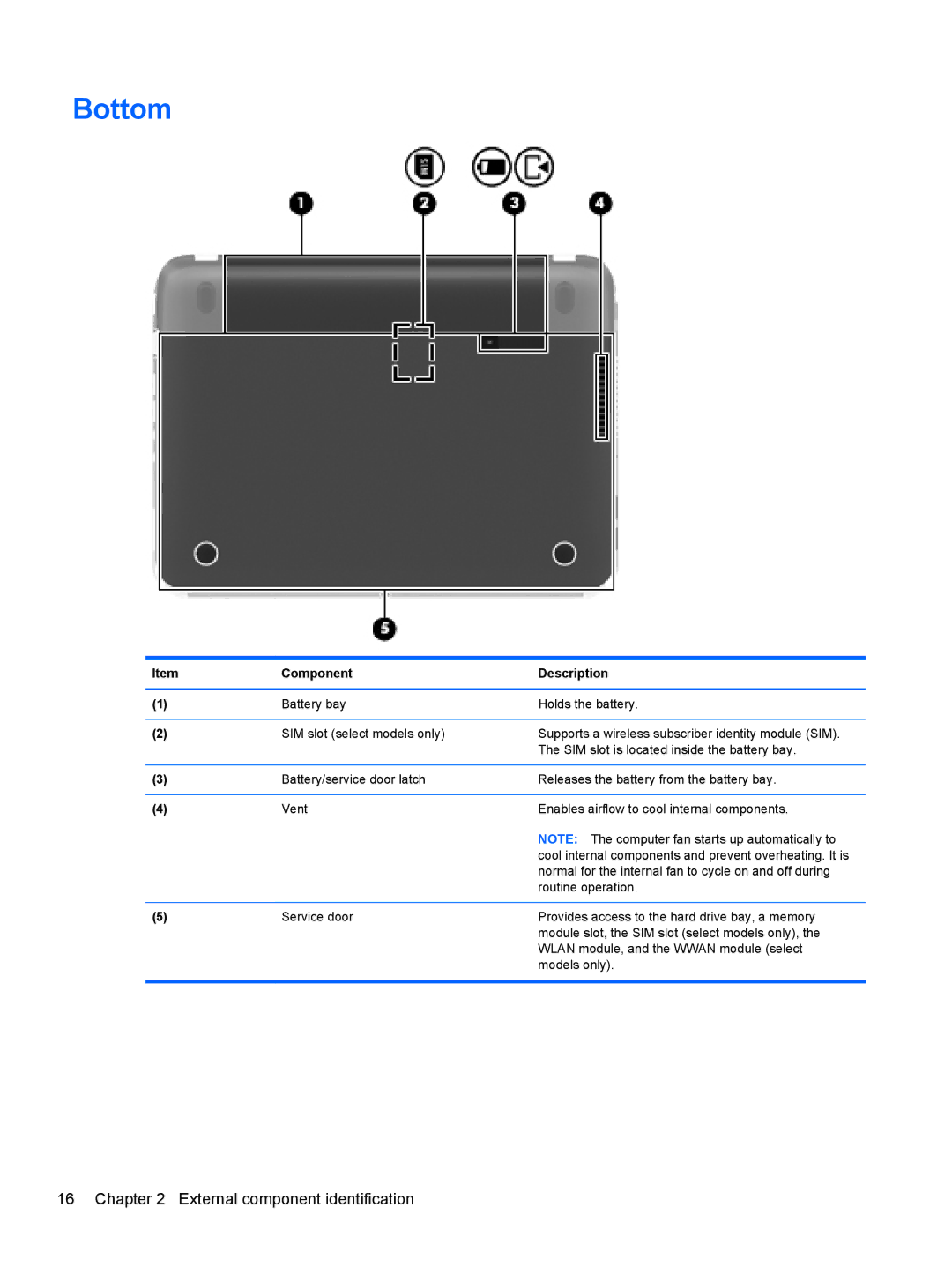
(1) | Battery bay | Holds the battery. |
|
|
|
(2) | SIM slot (select models only) | Supports a wireless subscriber identity module (SIM). |
|
| The SIM slot is located inside the battery bay. |
|
|
|
(3) | Battery/service door latch | Releases the battery from the battery bay. |
|
|
|
(4) | Vent | Enables airflow to cool internal components. |
|
| NOTE: The computer fan starts up automatically to |
|
| cool internal components and prevent overheating. It is |
|
| normal for the internal fan to cycle on and off during |
|
| routine operation. |
|
|
|
(5) | Service door | Provides access to the hard drive bay, a memory |
|
| module slot, the SIM slot (select models only), the |
|
| WLAN module, and the WWAN module (select |
|
| models only). |
|
|
|