9.Disconnect the display panel cable from the system board (see Display assembly on page 63).
10.Remove the top cover (see Top cover on page 68).
When replacing the system board, be sure that the following components are removed from the defective system board and installed on the replacement system board:
●SIM (see SIM (select models only) on page 45)
●RTC battery (see RTC battery on page 53)
●Memory module (see Memory module on page 57)
●Power connector cable (see Power connector cable on page 75)
●Fan (see Fan on page 77)
●Heat sink (see Heat sink on page 78)
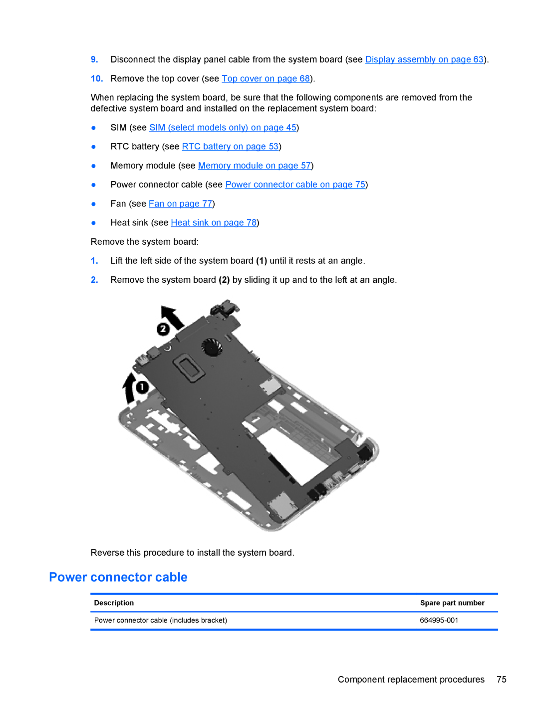
Remove the system board:
1.Lift the left side of the system board (1) until it rests at an angle.
2.Remove the system board (2) by sliding it up and to the left at an angle.
Reverse this procedure to install the system board.
Power connector cable
Description | Spare part number |
|
|
Power connector cable (includes bracket) | |
|
|
Component replacement procedures 75