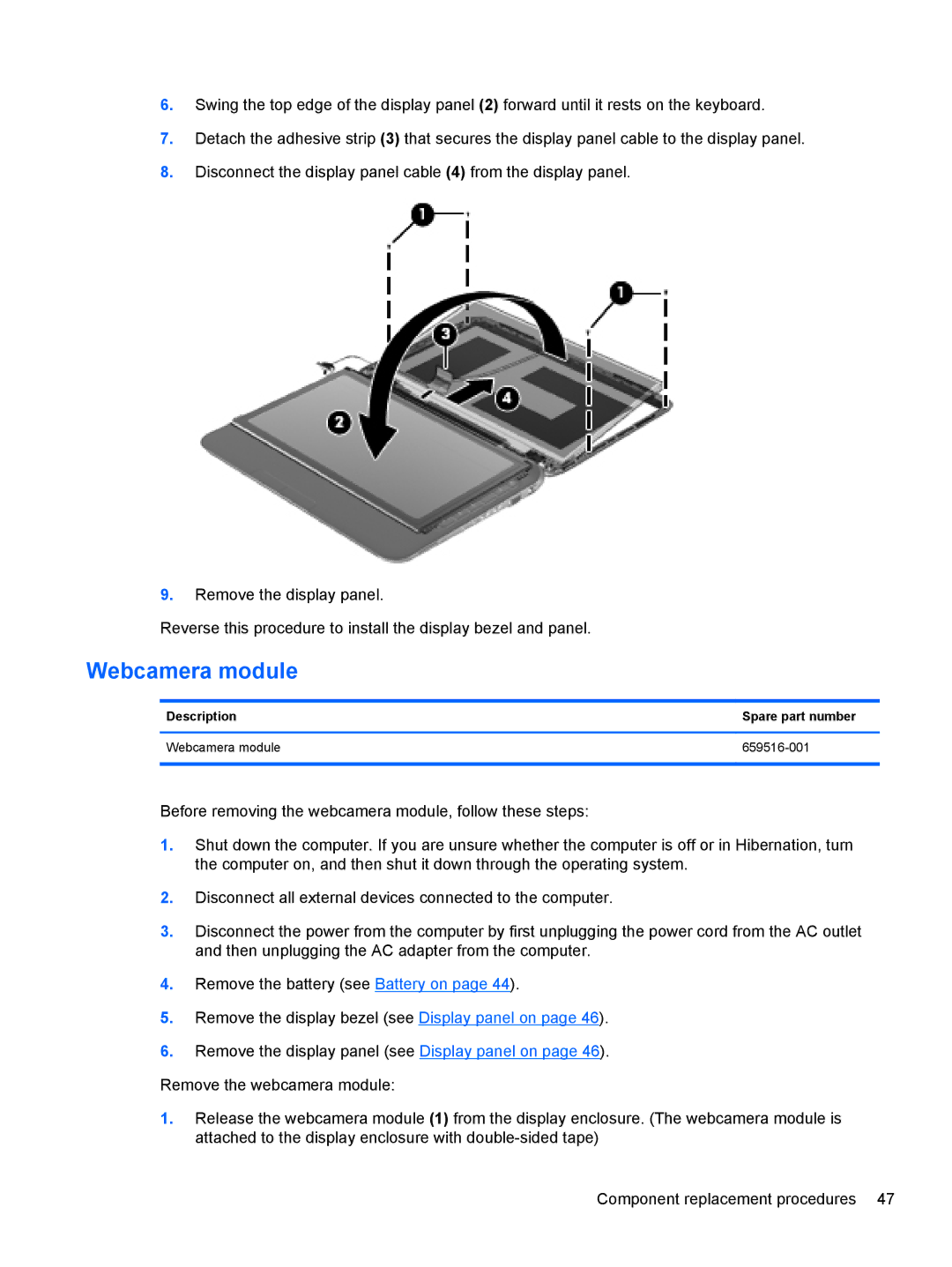
6.Swing the top edge of the display panel (2) forward until it rests on the keyboard.
7.Detach the adhesive strip (3) that secures the display panel cable to the display panel.
8.Disconnect the display panel cable (4) from the display panel.
9. Remove the display panel.
Reverse this procedure to install the display bezel and panel.
Webcamera module
Description | Spare part number |
|
|
Webcamera module |
|
|
|
Before removing the webcamera module, follow these steps:
1.Shut down the computer. If you are unsure whether the computer is off or in Hibernation, turn the computer on, and then shut it down through the operating system.
2.Disconnect all external devices connected to the computer.
3.Disconnect the power from the computer by first unplugging the power cord from the AC outlet and then unplugging the AC adapter from the computer.
4.Remove the battery (see Battery on page 44).
5.Remove the display bezel (see Display panel on page 46).
6.Remove the display panel (see Display panel on page 46).
Remove the webcamera module:
1.Release the webcamera module (1) from the display enclosure. (The webcamera module is attached to the display enclosure with
Component replacement procedures 47