![]() NOTE: Due to the adhesive quality of the thermal material located between the fan/heat sink assembly and system board components, it may be necessary to move the fan/heat sink assembly from side to side to detach the assembly.
NOTE: Due to the adhesive quality of the thermal material located between the fan/heat sink assembly and system board components, it may be necessary to move the fan/heat sink assembly from side to side to detach the assembly.
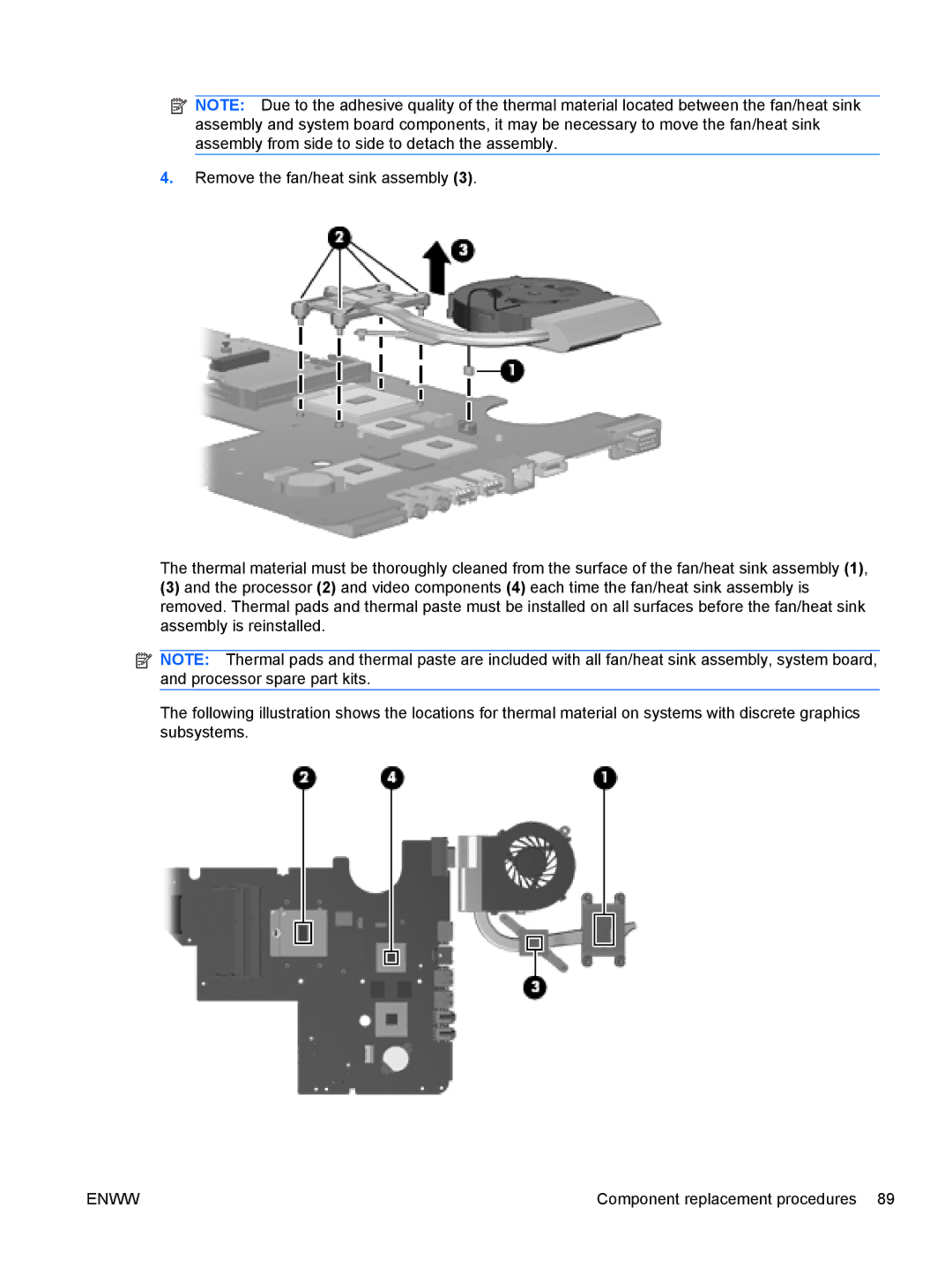
4.Remove the fan/heat sink assembly (3).
The thermal material must be thoroughly cleaned from the surface of the fan/heat sink assembly (1),
(3)and the processor (2) and video components (4) each time the fan/heat sink assembly is removed. Thermal pads and thermal paste must be installed on all surfaces before the fan/heat sink assembly is reinstalled.
![]() NOTE: Thermal pads and thermal paste are included with all fan/heat sink assembly, system board, and processor spare part kits.
NOTE: Thermal pads and thermal paste are included with all fan/heat sink assembly, system board, and processor spare part kits.
The following illustration shows the locations for thermal material on systems with discrete graphics subsystems.
ENWW | Component replacement procedures 89 |