Maintenance and Service Guide
Page
Safety warning notice
Contents
Illustrated Parts Catalog
Removal and Replacement Procedures
Vii
Product Description
Features
Product Description
Resetting the Computer
Power Management
Component Function
External Components
Front Components
Front Components
Left-Side Components
Left-Side Components
Right-Side Components
Right-Side Components
Keyboard Components
Keyboard Components
Fn key
Top Components, Part
Top Components, Part
Top Components, Part
Top Components, Part
Top Components, Part
Touchpad Components
Bottom Components
Bottom Components
Design overview
Setup Utility in Windows XP
Changing the Language of the Setup Utility
Navigating and Selecting in the Setup Utility
Displaying System Information
Restoring Default Settings in the Setup Utility
Select Exit Load Setup Defaults, and then press f10
Using Advanced Setup Utility Features
Closing the Setup Utility
Select To Do This
Main Menu
Main Menu
System Configuration Menu
System Configuration Menu
Security Menu
Security Menu
Diagnostics Menu
CD-ROM
Setup Utility in Windows Vista
Navigating and Selecting in the Setup Utility
Select Exit Load Setup Defaults, and then press enter
Setup Utility Menus
Main Menu
CD-ROM
Test
Diagnostics Menu
Option is called the Primary Hard Disk Self
Troubleshooting Flowcharts
Troubleshooting Flowcharts Overview
Flowchart 2.14-No OS Loading, Optical Drive
Flowchart 2.1-Initial Troubleshooting
Flowchart No Power Part
Flowchart 2.2-No Power, Part
Flowchart 2.3-No Power, Part
Flowchart 2.4-No Power, Part
External
Flowchart 2.5-No Power, Part
Flowchart 2.6-No Video, Part
Flowchart 2.7-No Video, Part
Flowchart No Video Part
Flowchart 2.8-Nonfunctioning Docking Device if applicable
Reseat power Cord in docking Device Power outlet
Flowchart 2.9-No Operating System OS Loading
Flowchart 2.10-No OS Loading, Hard Drive, Part
Loading
Flowchart 2.11-No OS Loading, Hard Drive, Part
Flowchart No OS Loading Hard Drive, Part
Flowchart 2.12-No OS Loading, Hard Drive, Part
Flowchart 2.13-No OS Loading, Diskette Drive
Flowchart 2.14-No OS Loading, Optical Drive
Flowchart 2.15-No Audio, Part
Flowchart 2.16-No Audio, Part
Flowchart 2.17-Nonfunctioning Device
Cmos
Flowchart 2.18-Nonfunctioning Keyboard
Flowchart 2.19-Nonfunctioning Pointing Device
Pointing device Not operating Properly Connect computer
Flowchart 2.20-No Network/Modem Connection
Illustrated Parts Catalog
Serial Number Location
Computer Major Components
Item Description Number
Speaker assembly
Spare Parts Computer Major Components
Computer Major Components
Display lid switch module includes display lid
Item Description Number Keyboards
Top cover support trim
Plastics Kit
Computer Major Components
System boards
Spare Part
13 USB/magnetic board includes USB/magnetic board cable
Computer Major Components
ExpressCard assembly
Optical drive connector board
Power connector assembly includes power
Description Number Processors include thermal pad
Computer Major Components
Description Number
Batteries
Computer Major Components
Item Description Number Mini Card modules
Computer Major Components
Spare Parts Computer Major Components
Computer Major Components
Spare Parts Computer Major Components
Computer Major Components
Item Description Number Optical drives include bezel
Description Number Display bezels
Display Assembly Components
Display Assembly Components Spare Part Number Information
Wireless antenna transceivers and cables
Display inverters
Camera module
Display panels
Mass Storage Devices
Mass Storage Devices Spare Part Number Information
Description Number Hard drives
Optical drives
Plastics Kit
Plastics Kit Spare Part Number Information
Item Description Number Plastics Kit 432981-001
Cable Kit
Cable Kit Spare Part Number Information
Item Description Number Cable Kit 434677-001
Miscellaneous
Spare Parts Miscellaneous
Description Number HP Remote Control
Remote control, ExpressCard
Wireless laser mouse
Power cords for use with all computer models
432983-001
Spare Part Number Description
Sequential Part Number Listing
Spare Parts Sequential Part Number Listing
South Korea
Netherlands
Spare Parts Sequential Part Number Listing
Spare Parts Sequential Part Number Listing
Dv9000
Model dv9000
Spare Parts Sequential Part Number Listing
Spare Part Number Description
Dv9200
Removal and Replacement Preliminaries
Tools Required
Service Considerations
Plastic Parts
Preventing Damage to Removable Drives
Preventing Electrostatic Damage
Packaging and Transporting Precautions
Workstation Precautions
Use the following grounding precautions at workstations
Grounding Equipment and Methods
Typical Electrostatic Voltage Levels
Static-Shielding Materials
Relative Humidity Event 10% 40% 55%
Material Use Voltage Protection Level
Removal and Replacement Procedures
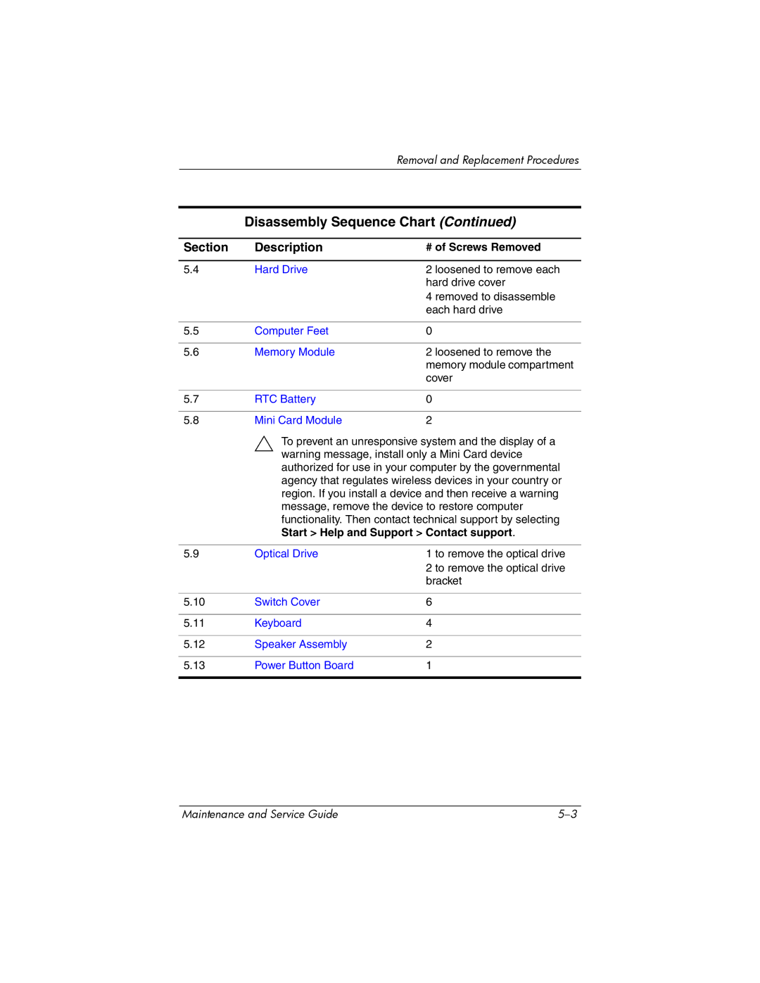
Disassembly Sequence Chart
Disassembly Sequence Chart
Serial Number
# of Screws Removed
RTC Battery Mini Card Module
Start Help and Support Contact support
System Board Fan/Heat Sink Assembly
Preparing the Computer For Disassembly
Battery Spare Part Number Information
Reverse the above procedure to install the battery
Hard Drive Bracket Kit
Hard Drive
Hard Drive Spare Part Number Information
Removing the Hard Drive Covers
Removing the Hard Drive
Removing the Hard Drive Bracket
Computer Feet
Memory Module
Memory Module Spare Part Number Information
Removing the Memory Module Compartment Cover
Reverse the above procedure to install a memory module
RTC Battery
RTC Battery Spare Part Number Information
Mini Card Module
Mini Card Module Spare Part Number Information
802.11b/g Wlan Mini Card module for use in the countries
Reverse the above procedure to install a Mini Card module
Optical Drive
Optical Drive Spare Part Number Information
Removing the Optical Drive
Removing the Optical Drive Bracket
Switch Cover
Switch Cover Spare Part Number Information
Releasing the Switch Cover
Reverse the above procedure to install the switch cover
Keyboard
Keyboard Spare Part Number Information
Removing the Keyboard Screw, Part
Removing the Keyboard Screws, Part
Releasing the Keyboard
Disconnecting the Keyboard Cable
Speaker Assembly
Speaker Assembly Spare Part Number Information
Reverse the above procedure to install the speaker assembly
Power Button Board
Power Button Board Spare Part Number Information
Removing the Power Button Board
Display Assembly
Display Assembly Spare Part Number Information
Removing the Display Assembly Screws
Disconnecting the Display Cables
Removing the Display Assembly
Removing the Display Bezel Screws
Display Assembly Subcomponents Spare Part Number Information
Removing the Camera Module
Removing the Display Inverter
Removing the Display Panel
Removing the Display Hinges
Removing the Wireless Antenna Transceivers and Cables
Removing the Microphones
Removing the Camera Cable
Top Cover
Top Cover Spare Part Number Information
Removing the Top Cover Screws, Part
Removing the Top Cover Screws, Part
Disconnecting the Top Cover Cables
Removing the Top Cover Screws, Part
Reverse the above procedure to install the top cover
Wireless Switch Board
Wireless Switch Board Spare Part Number Information
Removing the Wireless Switch Board
Removing the Wireless Switch Board
Audio Board
Audio Board Spare Part Number Information
Reverse the above procedure to install the audio board
Bluetooth Module
Bluetooth Module Spare Part Number Information
Reverse the above procedure to install the Bluetooth module
19 USB/Magnetic Board
USB/Magnetic Board Spare Part Number Information
Removing the USB/Magnetic Board
ExpressCard Assembly
ExpressCard Assembly Spare Part Number Information
Removing the ExpressCard Slot Bezel
Removing the ExpressCard Assembly
Top Cover Support Trim
Top Cover Support Trim Spare Part Number Information
Removing the Top Cover Support Trim Screws
Removing the Top Cover Support Trim
Display Lid Switch Module
Display Lid Switch Module Spare Part Number Information
Removing the Display Lid Switch Module
Power Connector Assembly
Power Connector Assembly Spare Part Number Information
Removing the Power Connector Assembly Bracket
Removing the USB Board
Releasing the Power Connector Assembly
System Board
System Board Spare Part Number Information
Removing the System Board Screw, Part
Removing the System Board Screws, Part
Removing the System Board
Removing the System Board Cables
25 Fan/Heat Sink Assembly
Fan/Heat Sink Assembly Spare Part Number Information
Removing the Fan/Heat Sink Assembly
Thermal Pad and Thermal Paste Locations
Removing the Heat Sink
Thermal Pad and Thermal Paste Locations
Processor
Processor Spare Part Number Information
Keyboard Section
Reverse the above procedure to install the processor
Computer
Dimensions
Stand-alone power requirements
Temperature
Relative humidity noncondensing
Maximum altitude unpressurized
Shock
Inch, WSXGA+, TFT Display
Inch, WXGA+, TFT Display
Hard Drives
100-GB 80-GB Dimensions
Primary 8-cell, Li-Ion Battery
Energy
DVD/CD-RW Combo Drive
Applicable disc Read Write
Center hole diameter
Disc diameter
Access time
Disc thickness
Track pitch
Audio output level
DVD±RW/R CD-RW Double-Layer Combo Drive
DVD-RW
System DMA
Hardware DMA System Function
System Interrupts
Hardware IRQ System Function
IRQ12
System I/O Addresses
Address hex
System I/O Addresses
NIC
System Memory Map
Memory Map Address hex
System Memory Map
Head
Color Qty Length Thread Width Silver Where used
Table A-1 Phillips PM3.0×3.0 Screw
Table A-2 Captive Phillips PM2.0×5.0 Screw
Head Color Qty. Length Thread Width
Color Qty Length Thread Width Silver 11.0 mm Where used
Table A-3 Phillips PM2.0×11.0 Screw
Color Qty Length Thread Width Black Where used
Table A-4 Phillips PM2.5×8.0 Screw
Table A-4 Phillips PM2.5×8.0 Screw
Table A-4 Phillips PM2.5×8.0 Screw
Table A-4 Phillips PM2.5×8.0 Screw
Table A-4 Phillips PM2.5×8.0 Screw
Table A-4 Phillips PM2.5×8.0 Screw
Table A-4 Phillips PM2.5×8.0 Screw
Phillips PM2.5×8.0 Screw Location
Table A-4 Phillips PM2.5×8.0 Screw
Table A-5 Phillips PM2.0×3.0 Screw
Table A-5 Phillips PM2.0×3.0 Screw
Table A-5 Phillips PM2.0×3.0 Screw
Table A-6 Phillips PM2.0×5.0 Screw
Table A-7 Phillips PM2.5×7.0 Screw
Table A-8 Silver Phillips PM2.5×5.0 Screw
Table A-8 Silver Phillips PM2.5×5.0 Screw
Table A-8 Silver Phillips PM2.5×5.0 Screw
Silver Phillips PM2.5×5.0 Screw Location
Table A-8 Silver Phillips PM2.5×5.0 Screw
Table A-8 Silver Phillips PM2.5×5.0 Screw
Table A-8 Silver Phillips PM2.5×5.0 Screw
Table A-8 Silver Phillips PM2.5×5.0 Screw
Table A-8 Silver Phillips PM2.5×5.0 Screw
Table A-9 Black Phillips PM2.5×5.0 Screw
Black Phillips PM2.5×5.0 Screw Location
Table A-10 Phillips PM2.0×4.0 Screw
Table A-11 Phillips PM2.5×6.0 Screw
Backup and Recovery in Windows XP
Recovering System Information
Backing Up Your Information
Using System Restore Points
Creating Recovery Discs
Restoring to a Previous Date and Time
Backup and Recovery in Windows XP
Reinstalling Software Programs and Drivers
Reinstalling Preinstalled Programs and Drivers
Performing a Recovery
Reinstalling Programs from Discs
Recovering from the Recovery Discs
Deleting the Recovery Partition on the Hard Drive
Select Start All Programs System Recovery PC Recovery
Updating Reinstalled Software
» Select Start Help and Support
Backup and Recovery in Windows Vista
Backup and Recovery in Windows Vista
Select Start Control Panel System and Maintenance System
Creating Recovery Discs
Select Start All Programs Recovery Manager Recovery Manager
Select Start Control Panel Programs Uninstall a program
Performing a Recovery
Deleting the Recovery Partition on the Hard Drive
Updating Reinstalled Software
Display Component Recycling
Display Component Recycling
Removing the Display Bezel Screw Covers and Screws
Removing the Display Bezel
Removing the Display Inverter Board
Removing the LCD Panel
Removing the LCD Panel Frame Screws
Removing the LCD Panel Frame
Removing the Backlight Cover
Releasing the Backlight Cables
Removing the Backlight Frame
Slide the backlight out of the backlight frame
Releasing the LCD Panel
Remove the LCD panel
Pin Signal
Table E-1 Universal Serial Bus
Table E-2 RJ-45 Network
Table E-3 Video-Out
Table E-4 External Monitor
Table E-5 RJ-11 Modem
Table E-6 Audio-In Microphone
Table E-7 Audio-Out Headphone
Power Cord Set Requirements
Conductor Power Cord Set
General Requirements
Country/Region Accredited Agency Applicable Note Number
Conductor Power Cord Set Requirements
Country/Region-Specific Requirements
Kema
Index
Index
Spare part number 3-9,3-37,5-62 ExpressCard slot
Index-4
Index-5
Troubleshooting 2-24,2-33num lock key
Index
Index-8
Index-9