Manuals
/
HP
/
Baby
/
Crib Toy
HP
Mobile 8510w
manual
Computer major components, Illustrated parts catalog
Models:
Mobile 8510w
1
26
171
171
Download
171 pages
61.49 Kb
23
24
25
26
27
28
29
30
Specifications
Install
Bluetooth
Pin Signal
Password
Symbols/Numerics
System Configuration menu
Diagnostics menu
Computer Setup
Cables and connectors
Page 26
Image 26
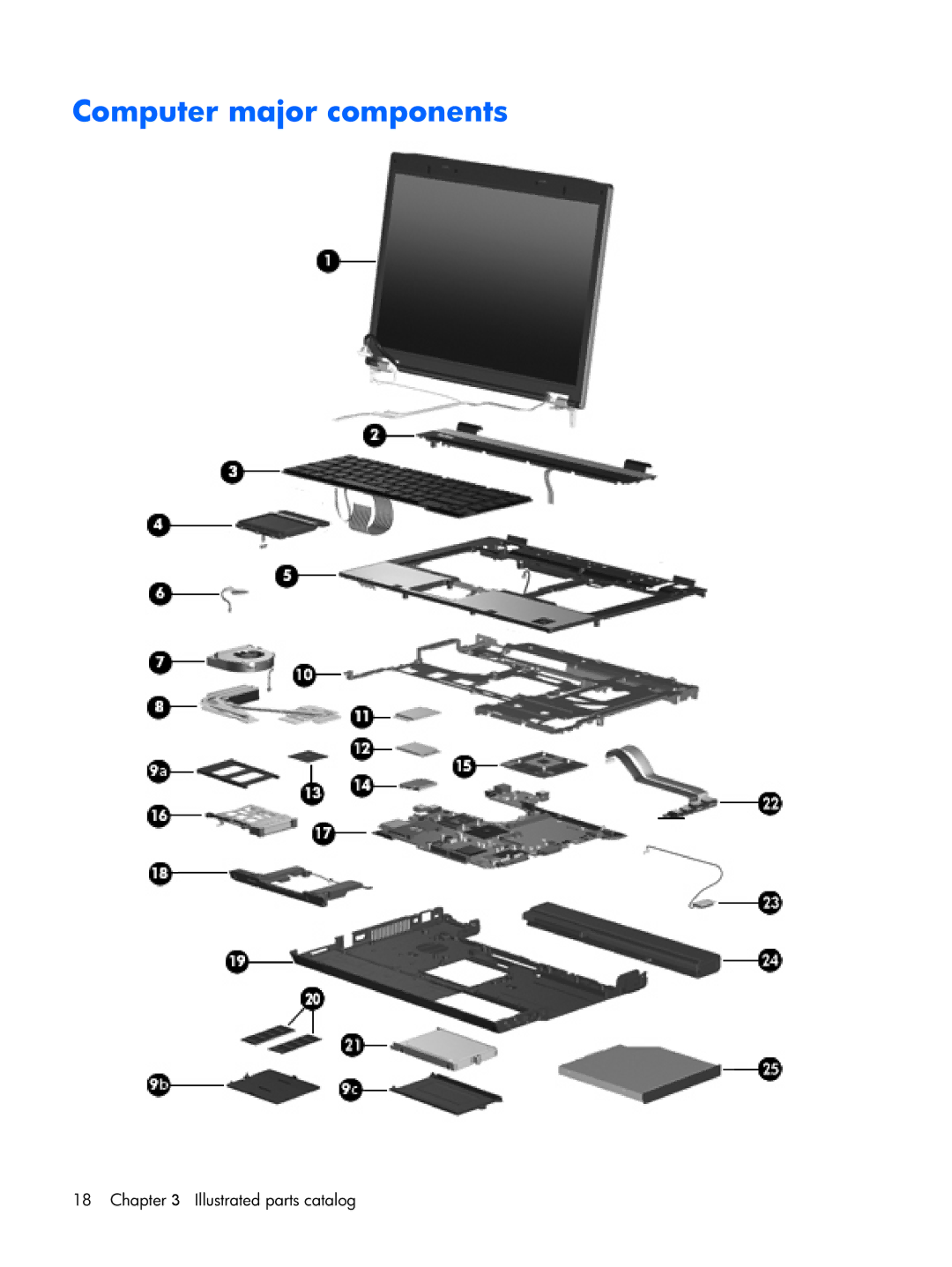
Computer major components
18 Chapter 3 Illustrated parts catalog
Page 25
Page 27
Page 26
Image 26
Page 25
Page 27
Contents
HP Compaq 8510w Mobile Workstation
First Edition June Document Part Number
Safety warning notice
Iv Safety warning notice
Table of contents
Computer Setup
Screw listing
Recycling
Product description
Category Description
Diskette drive
Hard drives
Optical drives
Microphone
Ethernet
Wireless Integrated Wlan options by way of wireless module
Integrated Wwan options by way of wireless module
Module
Preinstalled with Microsoft Office
Power requirements
Operating system Preinstalled
Restore Media
Certified
Serviceability End-user replaceable parts
Supported
Component Function
External component identification
Display components
Top components
Pointing devices
Windows XP, select Start Control Panel
Buttons, switches, and fingerprint reader
System and Maintenance Power Options
Keys
Fn key
Lights
Speaker volume
Front components
Left-side components
Rear components
Right-side components
Bottom components
Illustrated parts catalog
Serial number location
Computer major components
Illustrated parts catalog
Item Description Spare part Number
Display internal components
Keyboards without pointing stick
Description Spare part Number
Wlan modules
Intel Core Duo processors
Modem module
PC Card assembly
Speaker assembly
Optical drives include bezel
Plastics Kit
Item Description Spare part number Plastics Kit 452221-001
Cable Kit
Item Description Spare part number Cable Kit 452198-001
Mass storage devices
Miscellaneous parts
Sequential part number listing
Spare part Description Number
Sequential part number listing
Illustrated parts catalog
Wlan antenna transceivers and cables
Illustrated parts catalog
455077-001
Illustrated parts catalog
Service considerations
Removal and replacement procedures
Preliminary replacement requirements
Tools required
Cables and connectors
Grounding guidelines
Electrostatic discharge damage
Packaging and transporting guidelines
Equipment guidelines
Material Use Voltage protection level
Unknown user password
Component replacement procedures
Serial number
Computer feet
Battery
SIM
Display inverter
Page
Hard drive
Page
Page
Bluetooth module
Optical drive
Page
Memory module
Page
Keyboard
For use Spare part number
Page
Wwan module
Page
Fan
Description Spare part number Fan 452199-001
Heat sink
Page
Processor
Graphics card
Page
TouchPad
Page
Wlan module
Description Spare part number
Switch cover
Page
Page
RTC battery
Description Spare part number RTC battery 449137-001
Display assembly
DescriptionSpare part number
Page
Page
Page
Page
Top cover
Page
Speaker assembly
Description Spare part number Speaker assembly 452225-001
Page
Modem module
Description Spare part number Modem module 443899-001
System board and system board frame
Page
Page
RJ-11 connector cable
PC Card assembly
Description Spare part number PC Card assembly 455893-001
Page
USB/audio board
Page
Computer Setup
Starting Computer Setup
Restoring factory settings in Computer Setup
Using Computer Setup
Navigating and selecting in Computer Setup
Select To do this
Computer Setup menus
File menu
Diagnostics menu
Security menu
System Configuration menu
Windows operating system is not running
Computer Setup
Metric
Specifications
Computer specifications
Inch, Wuxga display specifications
Inch, WSXGA+ display specifications
Inch, Wxga display specifications
Hard drive specifications
160-GB 120-GB 100-GB 80-GB
DVD±RW and CD-RW Double-Layer Combo Drive specifications
DVD/CD-RW Combo Drive specifications
Applicable disc Read Write
Cache buffer
DVD-ROM Drive
Applicable disc
System DMA specifications
Hardware DMA System function
System interrupt specifications
Hardware IRQ System function
System I/O address specifications
Address hex System function shipping configuration
VGA
System memory map specifications
Size Memory address System function
Screw listing
Phillips PM2.0×5.0 captive screw
Color Quantity Length Thread Head diameter Black
Phillips PM2.0×11.0 captive screw
Color Quantity Length Thread Head diameter Silver 11.0 mm
Phillips PM3.0×4.0 screw
Color Quantity Length Thread Head diameter Silver
Torx T8M2.5×9.0 screw
Page
Silver Phillips PM2.0×3.0 screw
Page
Phillips PM2.5×9.0 captive screw
Phillips PM2.0×6.0 screw
Phillips PM2.5×4.0 screw
Page
Phillips PM2.0×2.0 screw
Torx T8M2.5×6.0 screw
Color Quantity Length Thread Heat width Black
Where used
Torx T8M2.5×7.0 screw
Color Quantity Length Thread Head diameter Silver 5mm
Phillips PM2.0×4.0 screw
Black Phillips PM2.5×7.0 screw
Phillips PM2.5×3.0 screw
Silver Phillips PM2.5×7.0 screw
Hex Metric HM5.0×10.0 screw lock
Color Quantity Length Thread Head diameter Silver 10.0 mm
Black Phillips PM2.0×3.0 screw
Backup and recovery in Windows Vista
Creating recovery discs
Backing up your information
When to back up
Backup suggestions
Backing up specific files or folders
Backing up the entire hard drive
Creating recovery points
Scheduling backups
Performing a recovery from the hard drive
Performing a recovery
Performing a recovery from the recovery discs
Initiating a recovery in Windows
Backup and recovery in Windows XP
Backing up your information
Backing up specific files or folders
Creating recovery points
Performing a recovery
Initiating a recovery in Windows
Audio-out headphone
Connector pin assignments
Pin Signal
Audio-in microphone
External monitor
RJ-11 modem
RJ-45 network
Universal Serial Bus
Power cord set requirements
Requirements for all countries and regions
Requirements for specific countries and regions
Country/region Accredited agency Applicable note number
Display
Battery
Recycling
Page
Page
Page
Page
Page
Symbols/Numerics
Index
Fan
Hdmi
Product description Audio
Top
Page
Image
Contents