
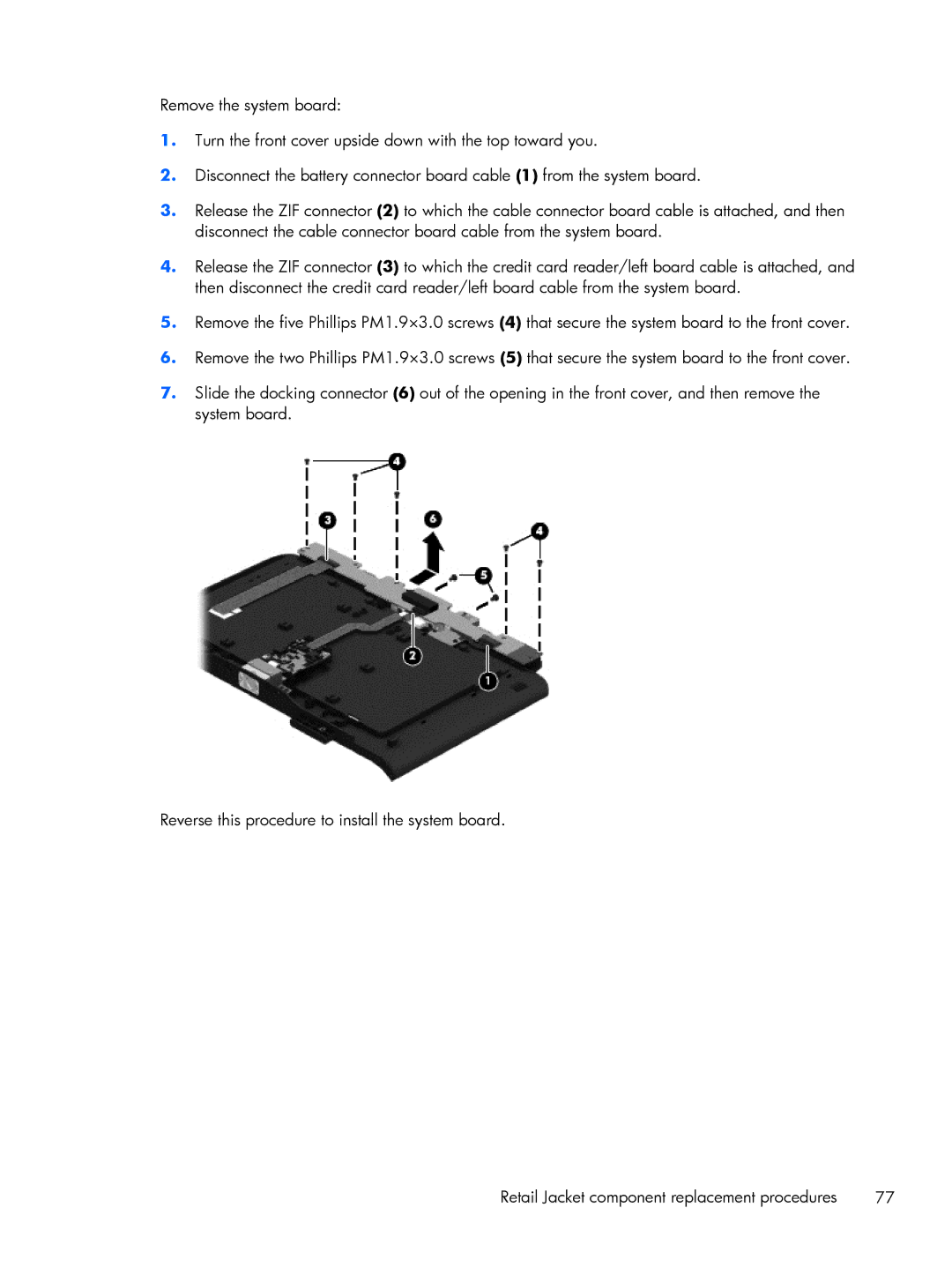
Mobile POS G2 Solution, Mobile POS G1 Solution specifications
In the rapidly evolving landscape of retail and service industries, the need for robust mobile point-of-sale (mPOS) solutions has become increasingly pronounced. HP's Mobile POS G1 and G2 Solutions stand out as two of the leading systems designed to cater to the demands of modern businesses. These solutions integrate cutting-edge technology with user-centric design, offering a seamless transaction experience for both businesses and customers.The HP Mobile POS G1 Solution pioneers in its ability to enhance operational efficiency and customer engagement. One of its main features is the compact and ergonomic design, making it easy for staff to handle while providing a range of functionalities. It is powered by a durable tablet interface, which runs on Windows operating systems, allowing for familiar navigation and integration with existing software.
For payment processing, the G1 solution supports various methods, including traditional card swipes, contactless payments, and mobile wallets, ensuring flexibility for customers. Its robust security features, including end-to-end encryption, help protect sensitive transaction data, instilling confidence in both businesses and their clients.
On the other hand, the HP Mobile POS G2 Solution builds on the success of its predecessor by incorporating even more advanced features and enhanced technologies. It features improved processing power with faster CPUs and greater RAM capacity, allowing for smooth multitasking and quick transaction times. Its state-of-the-art display offers a crisp and vibrant user interface, enhancing the overall customer experience.
The G2 solution also introduces advanced connectivity options, such as improved Wi-Fi and Bluetooth capabilities, enabling seamless integration with a variety of peripherals like barcode scanners and printers. Moreover, the G2 is equipped with a more robust battery life, ensuring that the device can handle long shifts without requiring frequent recharging.
Both the G1 and G2 solutions emphasize mobility, ensuring that staff can efficiently serve customers from anywhere in the store or venue. They are designed to support various retail and hospitality environments, providing the versatility that modern businesses require.
In conclusion, HP's Mobile POS G1 and G2 solutions represent effective tools in the realm of mobile transactions. With their combination of security, ease of use, and advanced technology, they empower businesses to enhance their efficiency while delivering exceptional customer service. Whether opting for the established G1 or the advanced G2, businesses can select a solution tailored to their specific needs, ensuring a competitive edge in an increasingly digital marketplace.