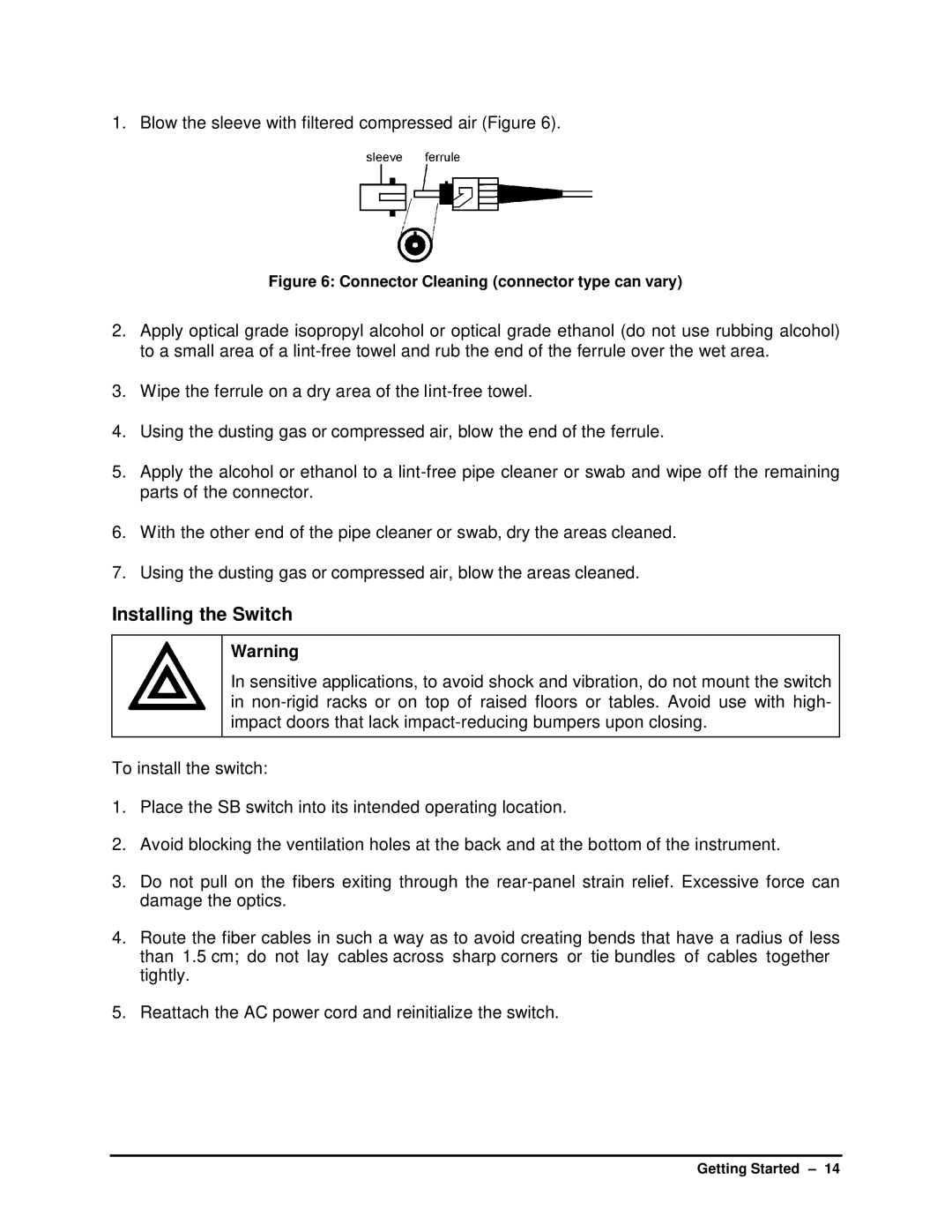
1. Blow the sleeve with filtered compressed air (Figure 6).
Figure 6: Connector Cleaning (connector type can vary)
2.Apply optical grade isopropyl alcohol or optical grade ethanol (do not use rubbing alcohol) to a small area of a
3.Wipe the ferrule on a dry area of the
4.Using the dusting gas or compressed air, blow the end of the ferrule.
5.Apply the alcohol or ethanol to a
6.With the other end of the pipe cleaner or swab, dry the areas cleaned.
7.Using the dusting gas or compressed air, blow the areas cleaned.
Installing the Switch
Warning
In sensitive applications, to avoid shock and vibration, do not mount the switch in
To install the switch:
1.Place the SB switch into its intended operating location.
2.Avoid blocking the ventilation holes at the back and at the bottom of the instrument.
3.Do not pull on the fibers exiting through the
4.Route the fiber cables in such a way as to avoid creating bends that have a radius of less than 1.5 cm; do not lay cables across sharp corners or tie bundles of cables together tightly.
5.Reattach the AC power cord and reinitialize the switch.
Getting Started – 14
