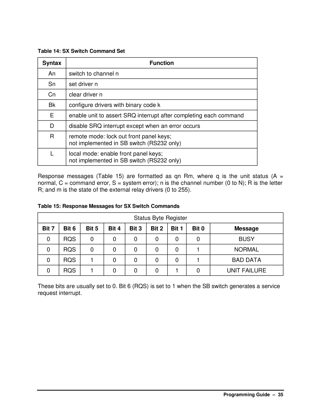
Table 14: SX Switch Command Set
Syntax | Function |
|
|
An | switch to channel n |
|
|
Sn | set driver n |
|
|
Cn | clear driver n |
|
|
Bk | configure drivers with binary code k |
|
|
E | enable unit to assert SRQ interrupt after completing each command |
|
|
D | disable SRQ interrupt except when an error occurs |
|
|
R | remote mode: lock out front panel keys; |
| not implemented in SB switch (RS232 only) |
|
|
L | local mode: enable front panel keys; |
| not implemented in SB switch (RS232 only) |
|
|
Response messages (Table 15) are formatted as qn Rm, where q is the unit status (A = normal, C = command error, S = system error); n is the channel number (0 to N); R is the letter R; and m is the state of the external relay drivers (0 to 255).
Table 15: Response Messages for SX Switch Commands
Status Byte Register
Bit 7 | Bit 6 | Bit 5 | Bit 4 | Bit 3 | Bit 2 | Bit 1 | Bit 0 | Message |
|
|
|
|
|
|
|
|
|
0 | RQS | 0 | 0 | 0 | 0 | 0 | 0 | BUSY |
|
|
|
|
|
|
|
|
|
0 | RQS | 0 | 0 | 0 | 0 | 0 | 1 | NORMAL |
|
|
|
|
|
|
|
|
|
0 | RQS | 1 | 0 | 0 | 0 | 0 | 1 | BAD DATA |
|
|
|
|
|
|
|
|
|
0 | RQS | 1 | 0 | 0 | 0 | 1 | 0 | UNIT FAILURE |
|
|
|
|
|
|
|
|
|
These bits are usually set to 0. Bit 6 (RQS) is set to 1 when the SB switch generates a service request interrupt.
Programming Guide – 35