Programming Guide
The following programming instructions for the SB switch are intended for users who are familiar with the GPIB interface and how to send or receive messages over a device. A detailed description of the GPIB interface is contained in ANSI/IEEE Std.
The SB switch is equipped with a GPIB parallel interface and an RS232C serial interface. The switch accepts the same device dependent commands (commands that control the instrument) over either interface.
The SB switch can be set to emulate the interface command sets, status reporting, and service request control of the SC Series and SX Series switches. The active interface command set is displayed when the switch is powered on. See the Setting the Interface Command Set section for instructions on changing the interface command set.
GPIB Pin Assignment
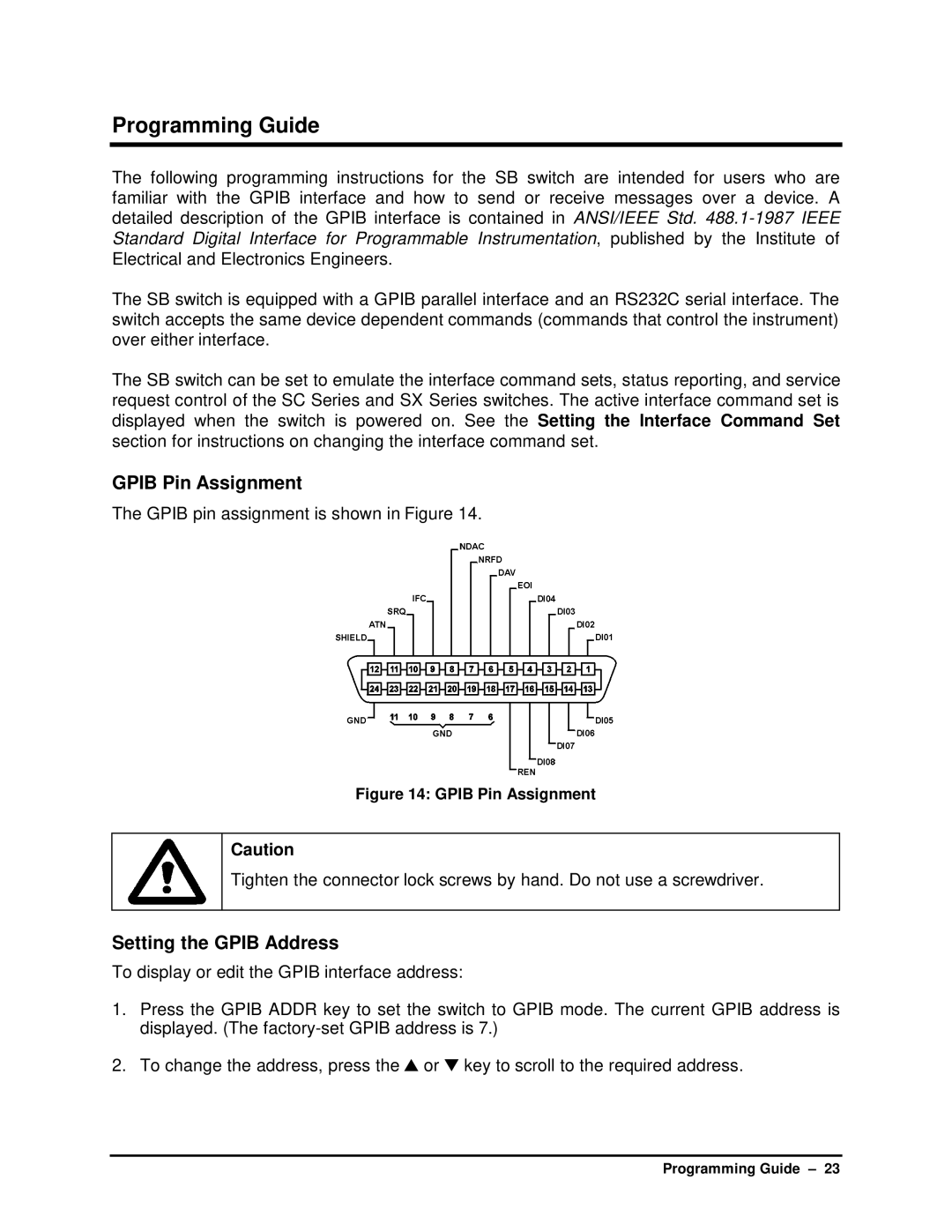
The GPIB pin assignment is shown in Figure 14.
Figure 14: GPIB Pin Assignment
Caution
Tighten the connector lock screws by hand. Do not use a screwdriver.
Setting the GPIB Address
To display or edit the GPIB interface address:
1.Press the GPIB ADDR key to set the switch to GPIB mode. The current GPIB address is displayed. (The
2.To change the address, press the ▲ or ▼ key to scroll to the required address.
Programming Guide – 23