To install and operate the switch successfully, ensure that:
•The primary AC input is
•The primary outlet is wired correctly, protected by a circuit breaker, and grounded in accordance with local electrical codes.
•The supply circuit, line fusing, and wire size are adequate, as specified by the electrical rating on the switch nameplate.
For additional power supply information, see the HP
Installing the SN6000B and SN3000B 16Gb FC Switches in a rack using the Rack Mount Kit
You can use the SN6000B and SN3000B Switch Rack Mount Kits to install your HP SN6000B and SN3000B 16Gb FC Switches in HP 10000 Series Racks.
CAUTION: Install the Rack Mount Kit as described in this section so that when the switch is installed, the port side faces the rear of the rack. This configuration optimizes performance by:
•Providing better airflow by using a plenum to force cool air to enter the switch from the front of the rack
•Providing room for a gradual bend in the fiber optic cables because the port side of the switch is set back from the edge of the rack
Use only the screws provided in the Rack Mount Kit. Using other screws can cause damage to internal components.
To install the switch in a rack using the Rack Mount Kit:
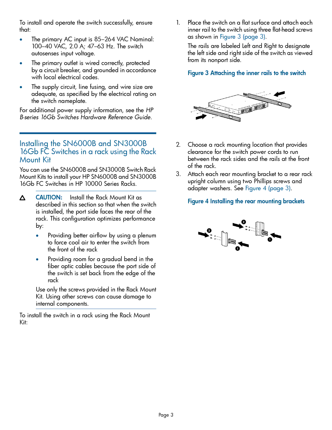
1.Place the switch on a flat surface and attach each inner rail to the switch using three
The rails are labeled Left and Right to designate the left side and right side of the switch as viewed from its nonport side.
Figure 3 Attaching the inner rails to the switch
2.Choose a rack mounting location that provides clearance for the switch power cords to run between the rack sides and the rails at the front of the rack.
3.Attach each rear mounting bracket to a rear rack upright column using two Phillips screws and adapter washers. See Figure 4 (page 3).
Figure 4 Installing the rear mounting brackets
Page 3