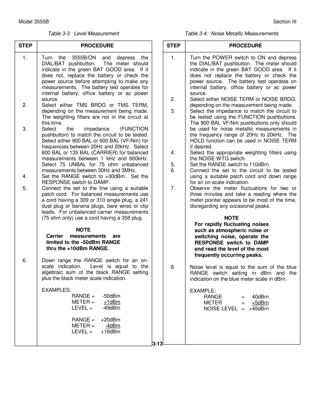
Model 3555B | Section III |
Table | Table |
STEP | PROCEDURE |
1.Turn the 3555B/ON and depress the DIAL/BAT pushbutton. The meter should indicate in the green BAT GOOD area. If it does not, replace the battery or check the power source before attempting to make any measurements. The battery test operates for internal battery, office battery or ac power source.
2.Select either TMS BRDG or TMS TERM, depending on the measurement being made. The weighting filters are not in the circuit at this time.
3.Select the impedance (FUNCTION pushbutton) to match the circuit to be tested. Select either 900 BAL or 600 BAL (VF/Nm) for frequencies between 20Hz and 20kHz. Select 600 BAL or 135 BAL (CARRIER) for balanced measurements between 1 kHz and 600kHz. Select 75 UNBAL for 75 ohm unbalanced measurements between 30Hz and 3MHz.
4.Set the RANGE switch to +30dBm. Set the RESPONSE switch to DAMP.
5.Connect the set to the line using a suitable patch cord. For balanced measurements use a cord having a 309 or 310 single plug, a 241 dual plug or banana plugs, bare wires or clip leads. For unbalanced carrier measurements (75 ohm only) use a cord having a 358 plug.
NOTE
Carrier measurements are limited to the
6.Down range the RANGE switch for an on-
scale indication. Level is equal to the algebraic sum of the black RANGE setting plus the black meter scale indication.
EXAMPLES:
RANGE = | |
METER = | +1dBm |
LEVEL = | |
RANGE = | +20dBm |
METER = | |
LEVEL = | +16dBm |
STEP | PROCEDURE |
1.Turn the POWER switch to ON and depress the DIAL/BAT pushbutton. The meter should indicate in the green BAT GOOD area. If it does not replace the battery or check the power source. The battery test operates on internal battery, office battery or ac power source.
2.Select either NOISE TERM or NOISE BRDG, depending on the measurement being made.
3.Select the impedance to match the circuit to be tested using the FUNCTION pushbuttons. The 900 BAL VF/Nm pushbuttons only should be used for noise metallic measurements in the frequency range of 20Hz to 20kHz. The HOLD function can be used in NOISE TERM if desired.
4.Select the appropriate weighting filters using the NOISE WTG switch.
5.Set the RANGE switch to 110dBrn.
6.Connect the set to the circuit to be tested using a suitable patch cord and down range for an
7.Observe the meter fluctuations for two or three minutes and take a reading where the meter pointer appears to be most of the time, disregarding any occasional peaks.
NOTE
For rapidly fluctuating noises such as atmospheric noise or switching noise, operate the RESPONSE switch to DAMP and read the level of the most frequently occurring peaks.
8.Noise level is equal to the sum of the blue RANGE switch setting in dBrn and the indication on the blue meter scale in dBrn.
EXAMPLE: |
|
|
RANGE | = | 40dBrn |
METER | = | +5dBrn |
NOISE LEVEL | = | +45dBrn |
