Model 3555B |
|
| Table of Contents | |||
|
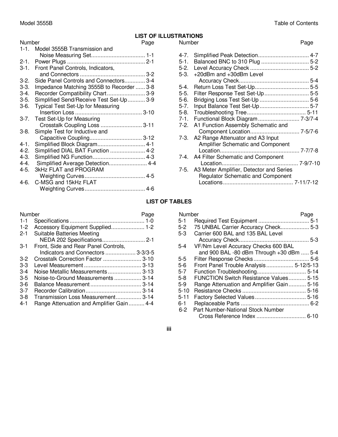
| LIST OF ILLUSTRATIONS |
|
| ||
Number | Page | Number |
| Page | ||
|
|
|
|
| ||
| Noise Measuring Set | Simplified Peak Detection | ||||
Power Plugs | Balanced BNC to 310 Plug | |||||
| Level Accuracy Check | |||||
| and Connectors | +20dBm and +30dBm Level |
|
| ||
| Accuracy Check | |||||
| ...... | Return Loss Test | ||||
Recorder Compatibility Chart | Filter Response Test | |||||
Bridging Loss Test | ||||||
| Input Balance Test | |||||
| Insertion Loss | Troubleshooting Tree | ||||
| Functional Block Diagram | |||||
| Crosstalk Coupling Loss | A1 Function Assembly Schematic and |
|
| ||
|
| Component Location | ||||
| Capacitive Coupling | A2 Range Attenuator and A3 Input |
|
| ||
Simplified Block Diagram |
| Amplifier Schematic and Component |
|
| ||
| Location | |||||
Simplified NG Function | A4 Filter Schematic and Component |
|
| |||
Simplified Average Detection |
| Location | ||||
|
|
| ||||
| Weighting Curves |
| Regulator Schematic and Component |
|
| |
|
| Locations | ||||
| Weighting Curves |
|
|
|
| |
|
| LIST OF TABLES |
|
|
| |
Number | Page | Number |
| Page | ||
Specifications | Required Test Equipment | |||||
Accessory Equipment Supplied | 75 UNBAL Carrier Accuracy Check | |||||
Suitable Batteries Meeting |
|
|
| |||
| NEDA 202 Specifications |
| Accuracy Check | |||
|
|
| ||||
| Indicators and Connectors |
| and 900 BAL | ..... | ||
Crosstalk Correction Factor | Filter Response Checks | |||||
Level Measurement | Front Panel Trouble Analysis |
| ||||
Noise Metallic Measurements | Function Troubleshooting | |||||
FUNCTION Switch Resistance Values | ||||||
Balance Measurement | Range Attenuation and Amplifier Gain | |||||
Recorder Calibration | Resistance Checks | |||||
Transmission Loss Measurement | Factory Selected Values | |||||
Replaceable Parts | ||||||
|
|
|
|
| ||
|
|
|
| Cross Reference Index | ||
Page 4
Image 4
