Section V
Table
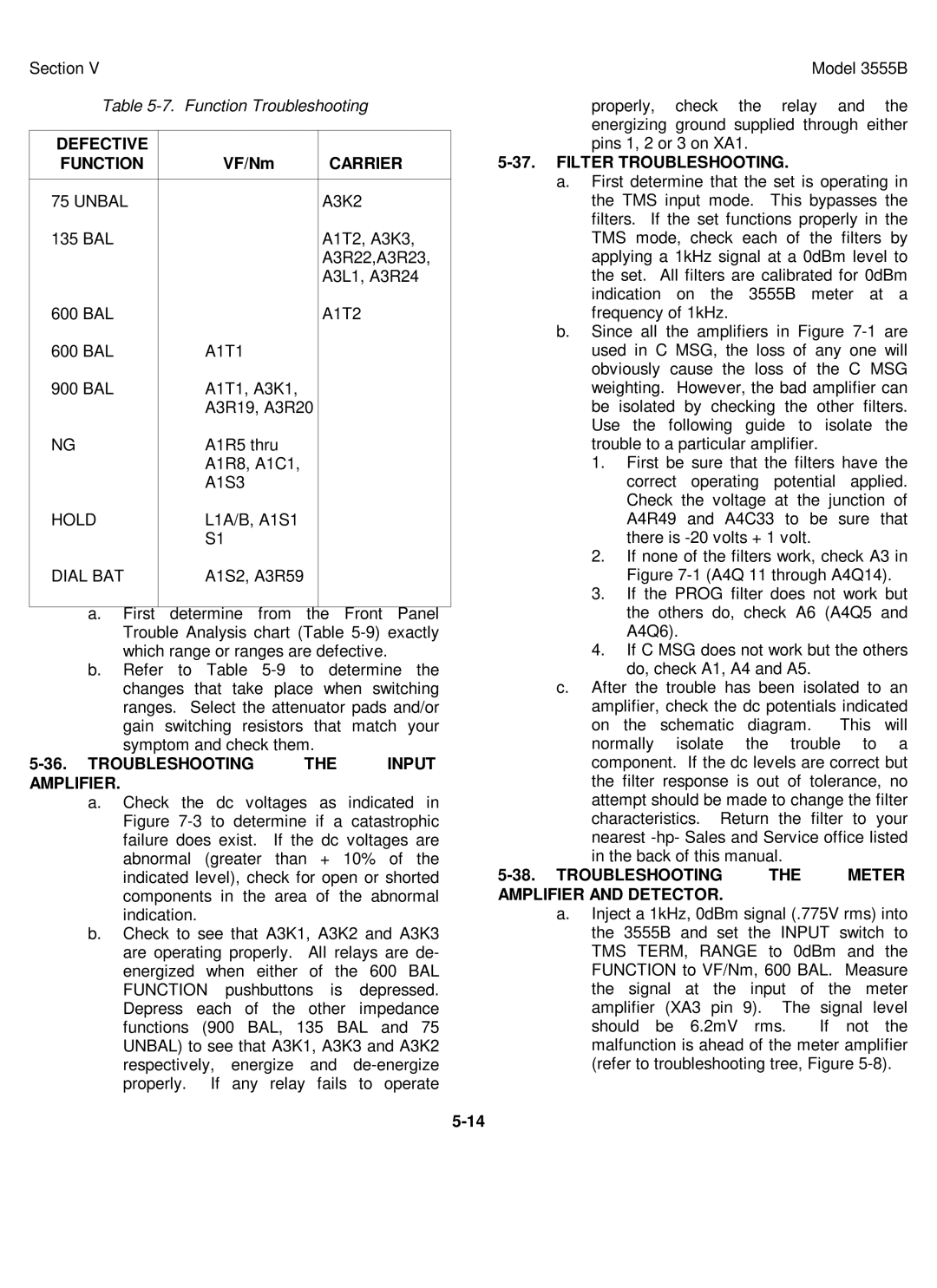
DEFECTIVE |
|
|
FUNCTION | VF/Nm | CARRIER |
|
|
|
75 UNBAL |
| A3K2 |
135 BAL |
| A1T2, A3K3, |
|
| A3R22,A3R23, |
|
| A3L1, A3R24 |
600 BAL |
| A1T2 |
600 BAL | A1T1 |
|
900 BAL | A1T1, A3K1, |
|
| A3R19, A3R20 |
|
NG | A1R5 thru |
|
| A1R8, A1C1, |
|
| A1S3 |
|
HOLD | L1A/B, A1S1 |
|
| S1 |
|
DIAL BAT | A1S2, A3R59 |
|
a.First determine from the Front Panel Trouble Analysis chart (Table
b.Refer to Table
| THE | INPUT |
AMPLIFIER. |
|
|
a.Check the dc voltages as indicated in Figure
b.Check to see that A3K1, A3K2 and A3K3 are operating properly. All relays are de- energized when either of the 600 BAL FUNCTION pushbuttons is depressed. Depress each of the other impedance functions (900 BAL, 135 BAL and 75 UNBAL) to see that A3K1, A3K3 and A3K2 respectively, energize and
Model 3555B
properly, check the relay and the energizing ground supplied through either pins 1, 2 or 3 on XA1.
5-37. FILTER TROUBLESHOOTING.
a.First determine that the set is operating in the TMS input mode. This bypasses the filters. If the set functions properly in the TMS mode, check each of the filters by applying a 1kHz signal at a 0dBm level to the set. All filters are calibrated for 0dBm indication on the 3555B meter at a frequency of 1kHz.
b.Since all the amplifiers in Figure
1.First be sure that the filters have the correct operating potential applied. Check the voltage at the junction of A4R49 and A4C33 to be sure that there is
2.If none of the filters work, check A3 in Figure
3.If the PROG filter does not work but the others do, check A6 (A4Q5 and A4Q6).
4.If C MSG does not work but the others do, check A1, A4 and A5.
c.After the trouble has been isolated to an amplifier, check the dc potentials indicated
on the schematic diagram. This will normally isolate the trouble to a component. If the dc levels are correct but the filter response is out of tolerance, no attempt should be made to change the filter characteristics. Return the filter to your nearest
5-38. TROUBLESHOOTING THE METER AMPLIFIER AND DETECTOR.
a.Inject a 1kHz, 0dBm signal (.775V rms) into the 3555B and set the INPUT switch to TMS TERM, RANGE to 0dBm and the FUNCTION to VF/Nm, 600 BAL. Measure the signal at the input of the meter amplifier (XA3 pin 9). The signal level
should be 6.2mV rms. If not the malfunction is ahead of the meter amplifier (refer to troubleshooting tree, Figure