Model 3555B | Section III |
|
|
|
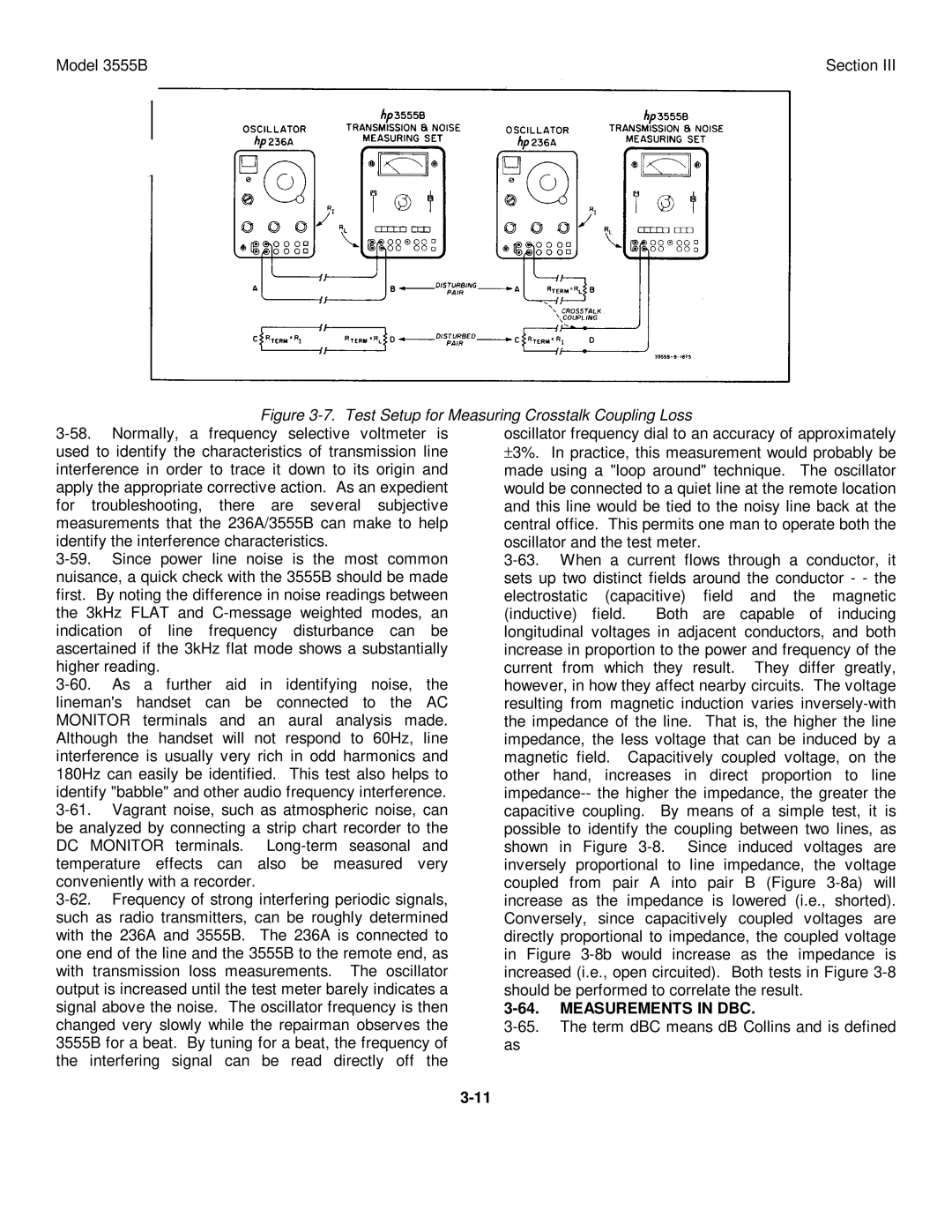
| Figure |
|
|
|
| ||||||
| oscillator frequency dial to an accuracy of approximately | |||||||||||||
used to identify the characteristics of transmission line | ±3%. | In practice, this measurement would probably be | ||||||||||||
interference in order to trace it down to its origin and | made using a "loop around" technique. | The oscillator | ||||||||||||
apply the appropriate corrective action. As an expedient | would be connected to a quiet line at the remote location | |||||||||||||
for troubleshooting, there are several subjective | and this line would be tied to the noisy line back at the | |||||||||||||
measurements that the 236A/3555B can make to help | central office. This permits one man to operate both the | |||||||||||||
identify the interference characteristics. |
|
| oscillator and the test meter. |
|
|
| ||||||||
|
| |||||||||||||
nuisance, a quick check with the 3555B should be made | sets up two distinct fields around the conductor - - the | |||||||||||||
first. By noting the difference in noise readings between | electrostatic (capacitive) field and the magnetic | |||||||||||||
the 3kHz FLAT and | (inductive) field. | Both | are | capable | of | inducing | ||||||||
indication of line frequency disturbance can be | longitudinal voltages in adjacent conductors, and both | |||||||||||||
ascertained if the 3kHz flat mode shows a substantially | increase in proportion to the power and frequency of the | |||||||||||||
higher reading. |
|
|
|
|
|
| current from which | they | result. | They | differ | greatly, | ||
As a | further | aid | in | identifying noise, | the | however, in how they affect nearby circuits. The voltage | ||||||||
lineman's handset can be connected to the AC | resulting from magnetic induction varies | |||||||||||||
MONITOR terminals and an aural analysis made. | the impedance of the line. | That is, the higher the line | ||||||||||||
Although the handset will not respond to 60Hz, line | impedance, the less voltage that can be induced by a | |||||||||||||
interference is usually very rich in odd harmonics and | magnetic field. Capacitively coupled voltage, on the | |||||||||||||
180Hz can easily be identified. | This test also helps to | other hand, increases in direct proportion to line | ||||||||||||
identify "babble" and other audio frequency interference. |
| |||||||||||||
| capacitive coupling. | By means of a simple test, it is | ||||||||||||
be analyzed by connecting a strip chart recorder to the | possible to identify the coupling between two lines, as | |||||||||||||
DC MONITOR | terminals. | shown in Figure | ||||||||||||
temperature effects can also be measured very | inversely proportional to line impedance, the voltage | |||||||||||||
conveniently with a recorder. |
|
|
|
| coupled from pair A into pair B (Figure | |||||||||
increase as the impedance is lowered (i.e., shorted). | ||||||||||||||
such as radio transmitters, can be roughly determined | Conversely, since capacitively coupled voltages are | |||||||||||||
with the 236A and 3555B. | The 236A is connected to | directly proportional to impedance, the coupled voltage | ||||||||||||
one end of the line and the 3555B to the remote end, as | in Figure | |||||||||||||
with | transmission loss | measurements. | The oscillator | increased (i.e., open circuited). Both tests in Figure | ||||||||||
output is increased until the test meter barely indicates a | should be performed to correlate the result. |
| ||||||||||||
signal above the noise. The oscillator frequency is then | MEASUREMENTS IN DBC. |
|
| |||||||||||
changed very slowly while the repairman observes the | ||||||||||||||
3555B for a beat. By tuning for a beat, the frequency of | as |
|
|
|
|
|
| |||||||
the interfering | signal | can | be | read | directly off | the |
|
|
|
|
|
|
| |
|
|
|
|
|
|
|
|
|
|
|
|
|
| |