Manuals
/
HP
/
Computer Equipment
/
Tablet Accessory
HP
tx2000 Computer major components, Item Description Spare part number, 1a Display assemblies
Models:
tx2000
1
23
126
126
Download
126 pages
42.24 Kb
20
21
22
23
24
25
26
27
Page 23
Image 23
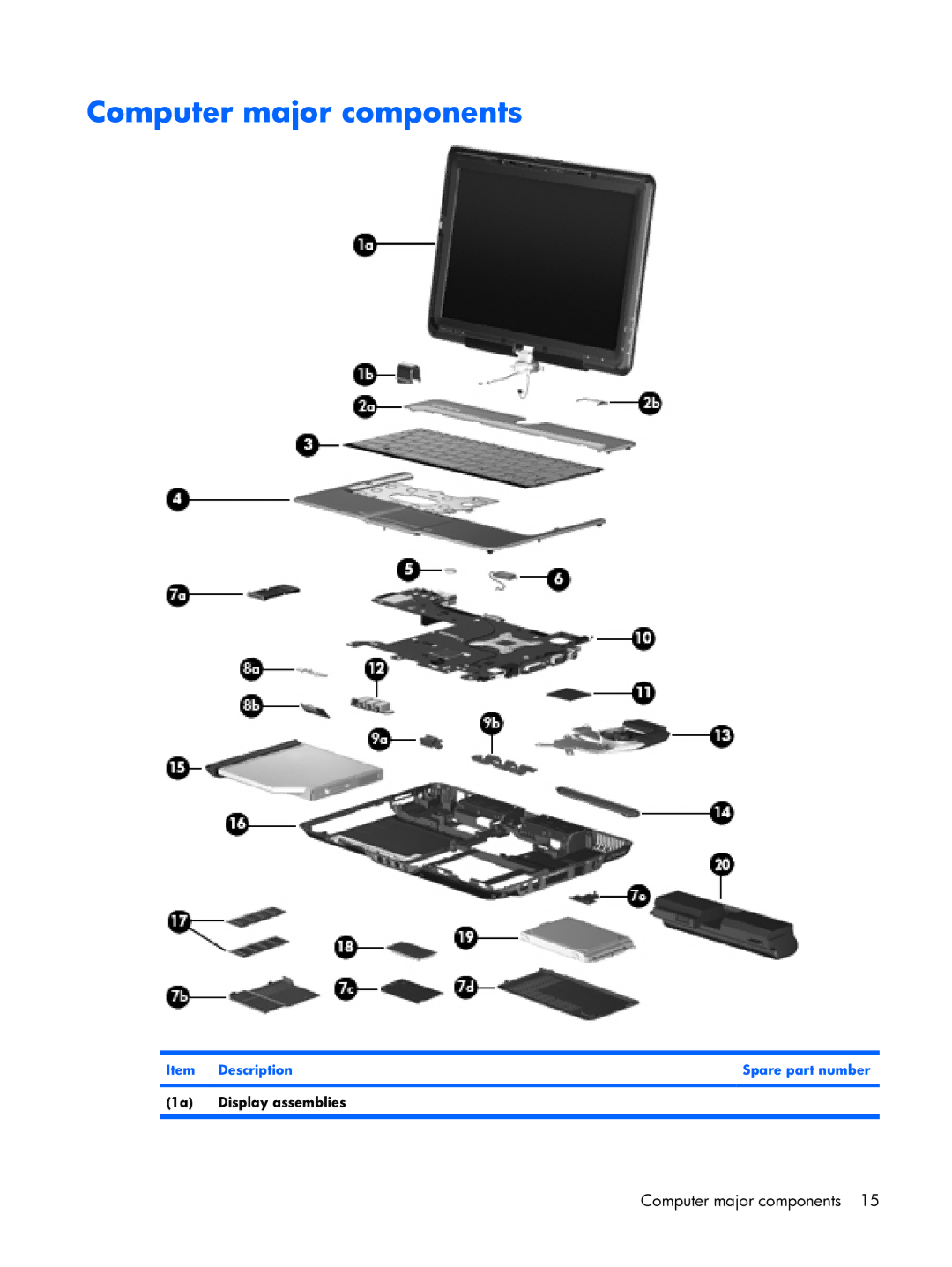
Computer major components
Item Description
Spare part number
(1a) Display assemblies
Computer major components 15
Page 22
Page 24
Page 23
Image 23
Page 22
Page 24
Contents
HP Pavilion tx2000 Entertainment PC
First Edition January Document Part Number
Safety warning notice
Iv Safety warning notice
Table of contents
Setup Utility
Screw listing
Index 114
Category Description
Product description
Audio
Optical drives
Web camera
Diskette drive
Docking
Power
Operating system Preinstalled
Serviceability End-user replaceable parts
Optical drive Wlan module
Component Function
External component identification
Top components
Display components
External component identification
Fn key
Keys
Pointing devices
Options
Control Panel System and Maintenance Power
Front components
Left-side components
Component Function Wireless light
Device and/or a Bluetooth device, is turned on
Amber All wireless devices are turned off
Right-side components
Vent Enables airflow to cool internal components
Rear components
Bottom components
Vents Enable airflow to cool internal components
Serial number location
Illustrated parts catalog
1a Display assemblies
Computer major components
Item Description Spare part number
Keyboards
Switch cover
RTC battery
Description Spare part number
Pen
Power switch board actuator
Plastics Kit
Pen holder
Illustrated parts catalog
Computer major components
Item Description Spare part number Plastics Kit 464114-001
Plastics Kit
Batteries
Mass storage devices
Miscellaneous parts
Spare part Description Number
Sequential part number listing
U.S. Virgin Islands, and the United States
Sequential part number listing
Pads
Antenna cables
Tools required
Removal and replacement procedures
Preliminary replacement requirements
Service considerations
Cables and connectors
Electrostatic discharge damage
Grounding guidelines
Packaging and transporting guidelines
Material Use Voltage protection level
Equipment guidelines
Unknown user password
Serial number
Component replacement procedures
Computer feet
Battery
Description Spare part number Pen 464146-001
Pen
Hard drive
Page
Optical drive
Memory module
Page
Wlan module
Removal and replacement procedures
Page
Page
Country or region Spare part number
Keyboard
Page
Switch cover
Page
Display assembly
Page
Page
Bumper pads
Top cover
464111-001
Page
Description Spare part number RTC battery 412390-001
RTC battery
Power switch assembly
Page
Bluetooth module
Hard drive see Hard drive on
System board
Page
Page
Pen holder
Audio/infrared board
Page
Fan/heat sink assembly
Page
Desription Spare part number
Processor
Page
Starting the Setup Utility
Setup Utility
Displaying system information
Changing the language of the Setup Utility
Navigating and selecting in the Setup Utility
Using advanced Setup Utility features
Restoring default settings in the Setup Utility
Security menu
Closing the Setup Utility
Setup Utility menus
Main menu
Called the Primary Hard Disk Self Test
System Configuration menu
Diagnostics menu
Metric
Specifications
Computer specifications
Inch, Wxga BrightView display specifications
320-GB 250-GB 160-GB 120-GB
Hard drive specifications
Write
Access time
Transfer mode
Applicable disc Read
Hardware DMA System function
System DMA specifications
Hardware IRQ System function
System interrupt specifications
Address hex System function shipping configuration
System I/O address specifications
VGA
Size Memory address System function
System memory map specifications
Color Quantity Length Thread Head width Silver
Screw listing
Phillips PM3.0×3.0 screw
Color Quantity Length Thread Head width Black
Phillips PM2.0×7.0 screw
Page
Phillips PM2.0×4.0 screw
Page
Phillips PM2.0×5.0 captive screw
Where used
Black Phillips PM2.0×3.0 screw
Color Quantity Length Thread Head width Black 11.0 mm
Phillips PM2.0×11.0 screw
Phillips PM2.5×6.0 screw
Silver Phillips PM2.0×3.0 screw
Page
Creating recovery discs
Backup and recovery
Recovering system information
Backing up your information
When to back up
Backup suggestions
Using system restore points
Page
Restore to a previous date and time
Recovering from the recovery discs
Performing a recovery
Audio-in microphone
Connector pin assignments
Pin Signal
Audio-out headphone
External monitor
RJ-45 network
RJ-11 modem
Universal Serial Bus
Video-out
Requirements for all countries or regions
Power cord set requirements
Region Accredited agency Applicable note number
Requirements for specific countries or regions
Recycling
Battery
Display
Page
Page
Page
Page
Page
DVD
Index
DVD±RW and CD-RW Double-Layer
Modem jack Location
System DMA
Top
Page
Image
Contents