Selecting the UPS voltage configuration
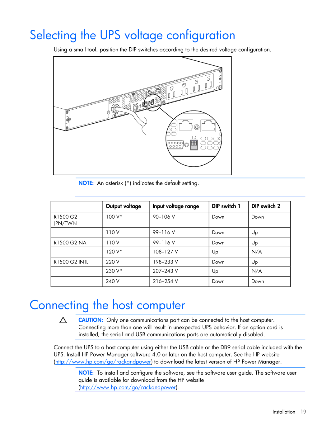
Using a small tool, position the DIP switches according to the desired voltage configuration.
NOTE: An asterisk (*) indicates the default setting.
| Output voltage | Input voltage range | DIP switch 1 | DIP switch 2 |
|
|
|
|
|
R1500 G2 | 100 V* | Down | Down | |
JPN/TWN |
|
|
|
|
|
|
|
|
|
| 110 V | Down | Up | |
|
|
|
|
|
R1500 G2 NA | 110 V | Down | Up | |
|
|
|
|
|
| 120 V* | Up | N/A | |
|
|
|
|
|
R1500 G2 INTL | 220 V | Down | Up | |
|
|
|
|
|
| 230 V* | Up | N/A | |
|
|
|
|
|
| 240 V | Down | Down | |
|
|
|
|
|
Connecting the host computer
CAUTION: Only one communications port can be connected to the host computer. Connecting more than one will result in unexpected UPS behavior. If an option card is installed, the serial and USB communications ports are automatically disabled.
Connect the UPS to a host computer using either the USB cable or the DB9 serial cable included with the UPS. Install HP Power Manager software 4.0 or later on the host computer. See the HP website (http://www.hp.com/go/rackandpower) to download the latest version of HP Power Manager.
NOTE: To install and configure the software, see the software user guide. The software user guide is available for download from the HP website (http://www.hp.com/go/rackandpower).