HP V4245US, V4201XX, V4200, V4000T, V4209TU, V4203XX, V4322EA, V4354EA, V4275EA, V4233TU Number 3-7,3-30

Models: V4333EA V4387EA V4332EA V4233TU V4200 V4332US V4320EA V4232TU V4325US V4212TU V4219TU V4354EA V4209TU V4220TU V4217EA V4218TU V4230TU V4322EA V4201XX V4376EA V4310NR V4245US V4000T V4382EA V4227TU V4335EA V4217TU V4275EA V4203XX V4377EA V4222TU V4223TU V4214TU

1 273
Download 273 pages 36.66 Kb
Page 272
Image 272

Index

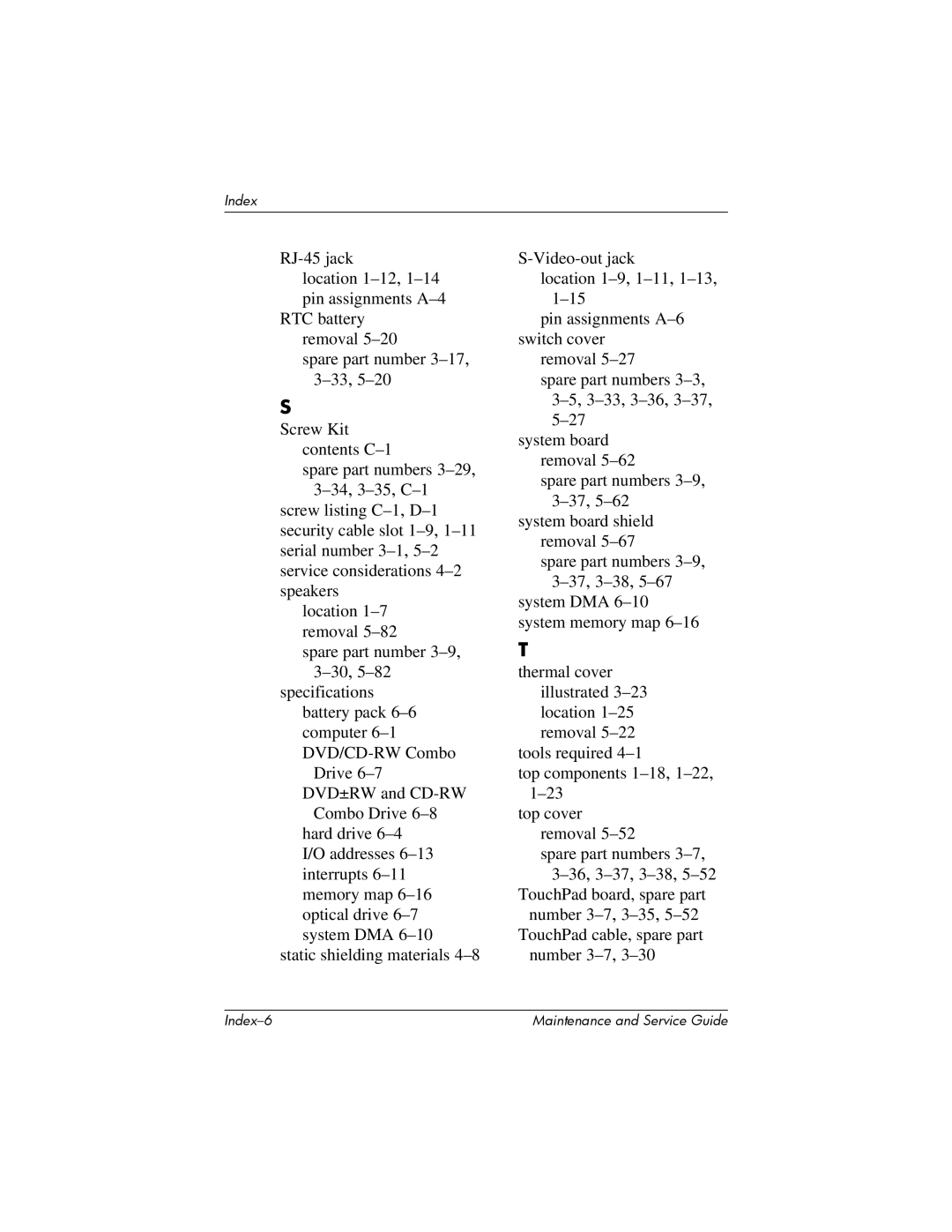
RJ-45 jack

location 1–12,1–14 pin assignments A–4

RTC battery removal 5–20

spare part number 3–17,3–33,5–20

S

Screw Kit contents C–1

spare part numbers 3–29,3–34,3–35,C–1

screw listing C–1,D–1 security cable slot 1–9,1–11serial number 3–1,5–2 service considerations 4–2 speakers

location 1–7 removal 5–82

spare part number 3–9,3–30,5–82

specifications battery pack 6–6 computer 6–1 DVD/CD-RW Combo

Drive 6–7 DVD±RW and CD-RW

Combo Drive 6–8 hard drive 6–4 I/O addresses 6–13 interrupts 6–11 memory map 6–16 optical drive 6–7 system DMA 6–10

static shielding materials 4–8

S-Video-out jack

location 1–9,1–11,1–13,1–15

pin assignments A–6 switch cover

removal 5–27

spare part numbers 3–3,3–5,3–33,3–36,3–37,5–27

system board removal 5–62

spare part numbers 3–9,3–37,5–62

system board shield removal 5–67

spare part numbers 3–9,3–37,3–38,5–67

system DMA 6–10 system memory map 6–16

T

thermal cover illustrated 3–23location 1–25 removal 5–22

tools required 4–1

top components 1–18,1–22,1–23

top cover removal 5–52

spare part numbers 3–7,3–36,3–37,3–38,5–52

TouchPad board, spare part number 3–7,3–35,5–52 TouchPad cable, spare part

number 3–7,3–30

Index–6

Maintenance and Service Guide

Page 272
Image 272
HP V4245US, V4201XX, V4200, V4000T, V4209TU, V4203XX, V4322EA, V4354EA, V4275EA, V4233TU, V4232TU, V4230TU, V4227TU Number 3-7,3-30