Maintenance and Service Guide
HP Pavilion Widescreen Notebook zt3000
HP Compaq Business Notebook nx7000 Compaq Presario Widescreen
Notebook PC
Maintenance and Service Guide HP Pavilion Widescreen Notebook zt3000
HP Compaq Business Notebook nx7000
Compaq Presario Widescreen Notebook PC Second Edition October
First Edition July Document Part Number
Contents
2 Troubleshooting
1 Product Description
3 Illustrated Parts Catalog
Contents
4 Removal and Replacement Preliminaries
5 Removal and Replacement Procedures
C Screw Listing Index
6 Specifications A Connector Pin Assignments
B Power Cord Set Requirements
Product Description
1.1 Models
HP Pavilion zt3000, HP Compaq nx7000 and Compaq Presario
Model Naming Conventions
Description
Maintenance and Service Guide
and Compaq Presario
HP Pavilion zt3000 Models
HP Pavilion zt3000, HP Compaq nx7000
People’s Republic
HP Pavilion zt3000 Models Continued
Product Description
Product Description
Maintenance and Service Guide
HP Pavilion zt3000 Models Continued
HP Compaq nx7000 Models
Product Description
Maintenance and Service Guide
HP Compaq nx7000 Models Continued
HP Compaq nx7000 Models Continued
Product Description
Maintenance and Service Guide
HP Compaq nx7000 Models Continued
1-10
HP Compaq nx7000 Models Continued
Product Description
1-11
Maintenance and Service Guide
HP Compaq nx7000 Models Continued
1-12
HP Compaq nx7000 Models Continued
Product Description
Maintenance and Service Guide
Compaq Presario X1000 Models
Product Description
1-13
1-14
Compaq Presario X1000 Models Continued
Product Description
Maintenance and Service Guide
Compaq Presario X1000 Models Continued
Product Description
1-15
1-16
Compaq Presario X1000 Models Continued
Product Description
Maintenance and Service Guide
Compaq Presario X1000 Models Continued
Product Description
1-17
1-18
Compaq Presario X1000 Models Continued
Product Description
Maintenance and Service Guide
Compaq Presario X1000 Models Continued
Product Description
1-19
1-20
Compaq Presario X1000 Models Continued
Product Description
Maintenance and Service Guide
Compaq Presario X1000 Models Continued
Product Description
1-21
1.2 Features
Support for the following optical drives
1.3 Clearing a Password
1.4 Power Management
1.5 External Components
Maintenance and Service Guide
Front and Left-Side Components
Product Description
Maintenance and Service Guide
Front and Left-Side Components
Component
Function
Maintenance and Service Guide
Rear Panel and Right-Side Components
Component
Function
Maintenance and Service Guide
Component
Function
Product Description
Maintenance and Service Guide
Keyboard Components
Product Description
1-30
Maintenance and Service Guide
Component
Function
num lk key
Top Components
Component
Function
Product Description
Maintenance and Service Guide
Top Components Continued
Component
Function
Bottom Components
Bottom Components
Component
Function
Maintenance and Service Guide
Bottom Components Continued
Component
Function
1.6 Design Overview
Troubleshooting
2.1 Computer Setup and Diagnostics Utilities
Using Computer Setup
Selecting from the File Menu
Maintenance and Service Guide
File Menu
Select
Selecting from the Security Menu
Troubleshooting
Security Menu
Select
Selecting from the Advanced Menu
Troubleshooting
Maintenance and Service Guide
Select
Troubleshooting
Advanced Menu Continued
Select
To Do This
2.2 Troubleshooting Flowcharts
Troubleshooting Flowcharts Overview
Flowchart
Troubleshooting
Flowchart 2.1-Initial Troubleshooting
Go to Flowchart No Power
Flowchart 2.2-No Power, Part
Power up
2. Ensure that the AC power source is active
Flowchart 2.8, Nonfunctioning Port Replicator
Flowchart 2.3-No Power, Part
Troubleshooting
power supply if applicable
2-10
Flowchart 2.4-No Power, Part
Continued from Flowchart 2.3, No Power, Part
power cord
active?
Flowchart 2.5-No Power, Part
Troubleshooting
2-12
items
Flowchart 2.6-No Video, Part
Flowchart 2.7-No Video, Part
Troubleshooting
Continued from Flowchart No Video, Part Remove
Maintenance and Service Guide
Flowchart 2.8-Nonfunctioning Port Replicator if applicable
Troubleshooting
Maintenance and Service Guide
2-15
2-16
Flowchart 2.9-No Operating System OS Loading
Troubleshooting
Flowchart 2.10-No OS Loading, Hard Drive, Part
Troubleshooting
Maintenance and Service Guide
Check the Setup utility for correct booting order
Flowchart 2.11-No OS Loading, Hard Drive, Part
System Restore
Flowchart 2.12-No OS Loading, Hard Drive, Part
2-20
Flowchart 2.13-No OS Loading, CD- or DVD-ROM Drive
Troubleshooting
Flowchart 2.14-No Audio, Part
Troubleshooting
Maintenance and Service Guide
2-21
Flowchart 2.15-No Audio, Part
Troubleshooting
driver in OS configured?
2-22
Flowchart 2.16-Nonfunctioning Device
Troubleshooting
Maintenance and Service Guide
Reseat device
Flowchart 2.17-Nonfunctioning Keyboard
Troubleshooting
Maintenance and Service Guide
2-24
Flowchart 2.18-Nonfunctioning Pointing Device
Troubleshooting
Maintenance and Service Guide
Reseat internal pointing device connector
Flowchart 2.19-No Network/Modem Connection
Troubleshooting
2-26
Replace jack or have jack activated
Illustrated Parts Catalog
3.1 Serial Number Location
3.2 Notebook Major Components
Maintenance and Service Guide
Notebook Major Components
Illustrated Parts Catalog
Maintenance and Service Guide
Item Description
Number
Illustrated Parts Catalog
Illustrated Parts Catalog
Maintenance and Service Guide
Notebook Major Components
Bluetooth wireless communications board
Maintenance and Service Guide
Spare Part
Description
Illustrated Parts Catalog
Maintenance and Service Guide
Notebook Major Components
PC Card assembly not illustrated
Left and right wireless antennae with cables
Maintenance and Service Guide
Spare Part
Illustrated Parts Catalog
Maintenance and Service Guide
Notebook Major Components
Battery pack, 8-cell, 4.4-wH
Maintenance and Service Guide
Spare Part
Description
3.3 Miscellaneous Plastics Kit Components
Maintenance and Service Guide
Miscellaneous Plastics Kit Components
Illustrated Parts Catalog
Miscellaneous Plastics Kit Components Spare Part Number
3.4 Miscellaneous Cable Kit Components
Maintenance and Service Guide
Miscellaneous Cable Kit Components
Item Description
3.5 Miscellaneous Doors/Covers Kit Components
Maintenance and Service Guide
Miscellaneous Doors/Covers Kit Components
Item Description
3.6 Mass Storage Devices
Mass Storage Devices
Item Description
Number
3.7 Miscellaneous
Power cords
Maintenance and Service Guide
Description
Power cords
Spare Part Information Continued
Miscellaneous not illustrated
Description
Removal and Replacement Preliminaries
4.1 Tools Required
Plastic Parts
4.2 Service Considerations
Cables and Connectors
4.3 Preventing Damage to Removable Drives
4.5 Packaging and Transporting Precautions
4.4 Preventing Electrostatic Damage
4.6 Workstation Precautions
4.7 Grounding Equipment and Methods
Removal and Replacement Preliminaries
Maintenance and Service Guide
Event
Material
Removal and Replacement Procedures
5.1 Serial Number
Removal and Replacement Procedures
Maintenance and Service Guide
Serial Number Location
5.2 Disassembly Sequence Chart
Removal and Replacement Procedures
Maintenance and Service Guide
# of Screws
5.3 Preparing the Notebook for Disassembly
Spare Part Number Information
c. Lift the front edge of the battery pack up and swing it back
d. Remove the battery pack
Reverse the above procedure to install the battery pack
Removing the Battery Pack
5. Remove the hard drive by following these steps
f. Remove the hard drive shield 2 and connector 3 from the hard drive
5.4 Notebook Feet
Replacing the Notebook Feet
5.5 Memory Expansion Board
Reverse the above procedure to install a memory expansion board
Removal and Replacement Procedures
Maintenance and Service Guide
7. Pull the board away from the socket at a 45-degree angle
5.6 Mini PCI Communications Board
Removing the Mini PCI Compartment Cover
8. Pull the board away from the socket at a 45-degree angle
5.7 RTC Battery
Removing the RTC battery
5.8 Optical Drive
Removing the Optical Drive
5.9 Keyboard
Removal and Replacement Procedures
Maintenance and Service Guide
Removing the Keyboard Screws
Removal and Replacement Procedures
Maintenance and Service Guide
4. Turn the notebook right-side up with the front facing you
5. Open the notebook
9. Remove the keyboard
5.10 Switch Cover
Removing the Switch Cover
5.11 Speaker Cover
Removing the Speaker Cover Screws
Reverse the above procedure to install the speaker cover
Removal and Replacement Procedures
Maintenance and Service Guide
7. Slide the speaker cover back 2 to disengage it from the notebook
5.12 Fan
Removing the Fan
5.13 Heat Sink
Reverse the above procedure to install the heat sink
Removal and Replacement Procedures
Maintenance and Service Guide
Removing the Thermal Grease From the Heat Sink and Processor
5.14 Processor
Removal and Replacement Procedures
Spare Part Number Information
5-24
Reverse the above procedure to install the processor
Removal and Replacement Procedures
Maintenance and Service Guide
3. Lift the processor straight up 2 and remove it
5.15 Display Assembly
Removal and Replacement Procedures
Spare Part Number Information
5-26
Disconnecting the Display Cable
Removal and Replacement Procedures
Maintenance and Service Guide
5. Disconnect the display video cable 2 from the system board
7. Remove the following screws
10. Lift the display assembly straight up and remove it
Reverse the above procedure to install the display assembly
Removing the Display Assembly
Removal and Replacement Procedures
5.16 Top Cover
Spare Part Number Information
Removal and Replacement Procedures
Maintenance and Service Guide
5. Remove the following screws
Three PM2.5×9.5 screws 1 along the front edge of the notebook
6. Turn the notebook right-side up with the rear panel facing you
Disconnecting the Bluetooth Wireless Module and Speaker Cables
11. Position the notebook so the front faces forward
Reverse the above procedure to install the top cover
Removal and Replacement Procedures
Maintenance and Service Guide
14. Remove the top cover
338134-01
5.17 Bluetooth Board
Bluetooth wireless communications board
3. Disconnect the Bluetooth board cable 1 from the Bluetooth board
5.18 SD Card Slot Board and Cable
Spare Part Number Information
2. Disconnect the SD Card slot board cable 1 from the system board
5.19 VGA Board and Shield
Removal and Replacement Procedures
Spare Part Number Information
5-40
4. Remove the VGA board and shield
5.20 Modem and Cable
Replacing the Thermal Pads on the VGA Board and Shield
Speaker cover Section Display assembly Section Top cover Section
5.21 System Board
Spare Part Number Information
Removal and Replacement Procedures
Maintenance and Service Guide
2. Disconnect the SD Card slot board cable 1 from the system board
Removing the System Board Screws
4. Lift the right side of the system board approximately
Specifications
Dimensions
Stand-alone power requirements
Temperature
Specifications
Notebook Continued
Relative humidity noncondensing
Shock
Specifications
Dimensions
Pixel resolution
Maintenance and Service Guide
Specifications
Dimensions
Pixel resolution
Number of colors
Specifications
Dimensions
Pixel resolution
Maintenance and Service Guide
Specifications
Dimensions
temperature
80-GB
Specifications
Weight
Power supply
Dimensions
Specifications
Access time
Applicable disc
Center hole diameter
Specifications
Access time
Maintenance and Service Guide
Applicable disc
Specifications
Access time
Applicable disc
Center hole diameter
Specifications
Access time
Maintenance and Service Guide
Applicable disc
Specifications
Hardware
System
Function
Specifications
Maintenance and Service Guide
Hardware
System
shipping configuration
Specifications
I/O Address
System Function
shipping configuration
Specifications
Maintenance and Service Guide
I/O Address
shipping configuration
Specifications
I/O Address
System Function
Connector Pin Assignments
Signal
Signal
Maintenance and Service Guide
Connector Pin Assignments
Signal
Signal
Signal
Connector Pin Assignments
Signal
Signal
Maintenance and Service Guide
Connector Pin Assignments
Signal
Signal
Signal
Connector Pin Assignments
Signal
Signal
Maintenance and Service Guide
General Requirements
Power Cord Set Requirements
3-Conductor Power Cord Set
Country-Specific Requirements
Power Cord Set Requirements
Applicable Note
Country
Power Cord Set Requirements
Maintenance and Service Guide
Applicable Note
Country
Screw Listing
Maintenance and Service Guide
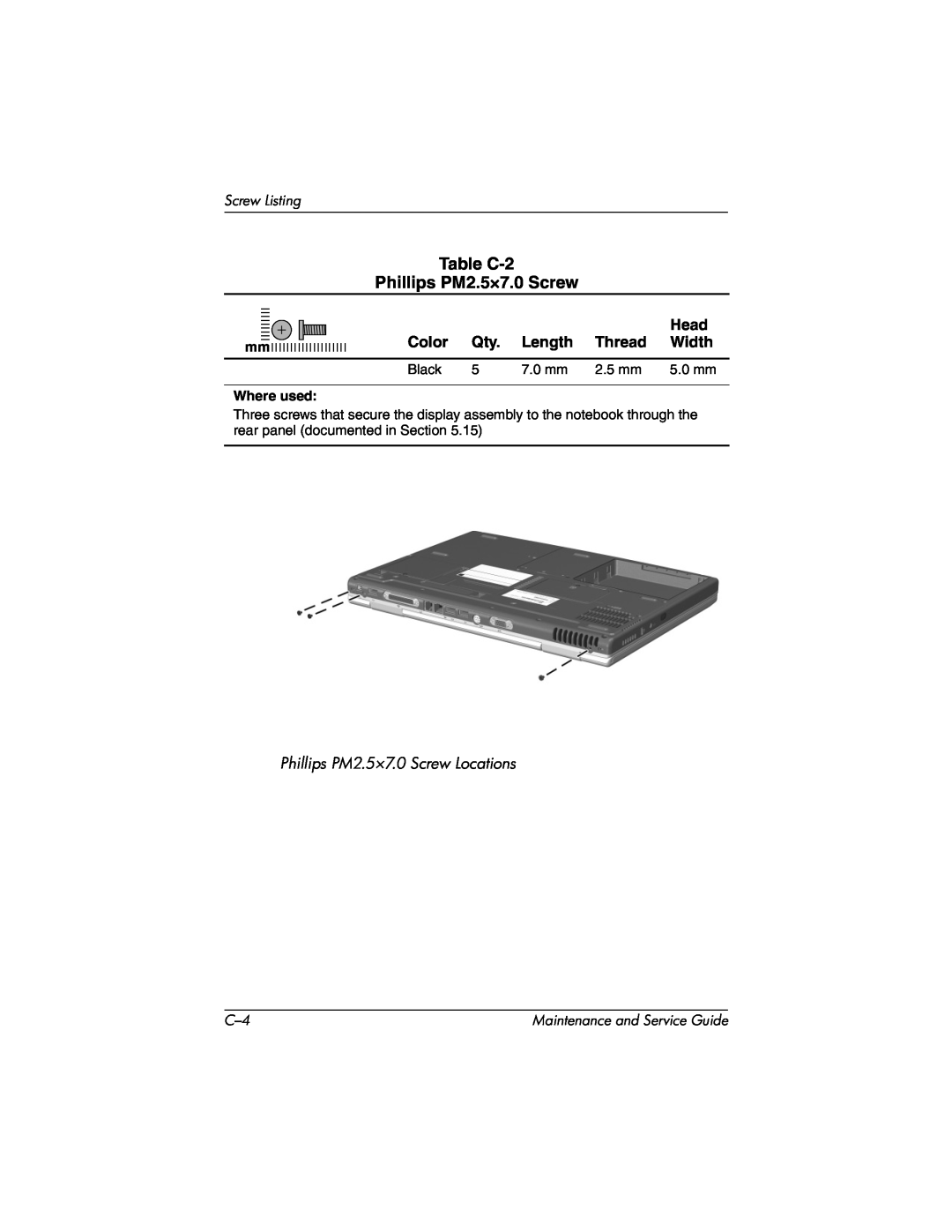
Where used
Head
Color
Length
Where used
Maintenance and Service Guide
Head Color Qty. Length Thread Width
Phillips PM2.5×7.0 Screw Locations
Where used
Maintenance and Service Guide
Head
Color
Where used
Maintenance and Service Guide
Head Color Qty. Length Thread Width
Phillips PM2.5×7.0 Screw Locations
Where used
Maintenance and Service Guide
Head
Color
Where used
Maintenance and Service Guide
Table C-4
Phillips PM2.5×5.0 Screw
Where used
Maintenance and Service Guide
Head Color Qty. Length Thread Width
Phillips PM2.5×5.0 Screw Locations
Where used
Maintenance and Service Guide
Head Color Qty. Length Thread Width
Phillips PM2.5×5.0 Screw Locations
Where used
Maintenance and Service Guide
Head Color Qty. Length Thread Width
Phillips PM2.5×5.0 Screw Locations
Where used
Maintenance and Service Guide
Head Color Qty. Length Thread Width
Phillips PM2.5×5.0 Screw Location
Where used
Maintenance and Service Guide
Head Color Qty. Length Thread Width
Phillips PM2.5×5.0 Screw Locations
Where used
Maintenance and Service Guide
Head Color Qty. Length Thread Width
Phillips PM2.5×5.0 Screw Location
Where used
Head
Color
Length
Where used
Maintenance and Service Guide
Table C-5
Phillips PM2.5×15.0 Screw Continued
Where used
Maintenance and Service Guide
Head
Color
Where used
Maintenance and Service Guide
Table C-6
Phillips PM2.5×3.0 Screw
Where used
Head
Color
Length
Where used
Maintenance and Service Guide
Table C-8
Phillips PM2.0×9.0 Spring-Loaded Screw
Where used
Maintenance and Service Guide
Head
Color
Index
Page
Page
Page
Index-5