OPERATION
Know Your Air Compressor
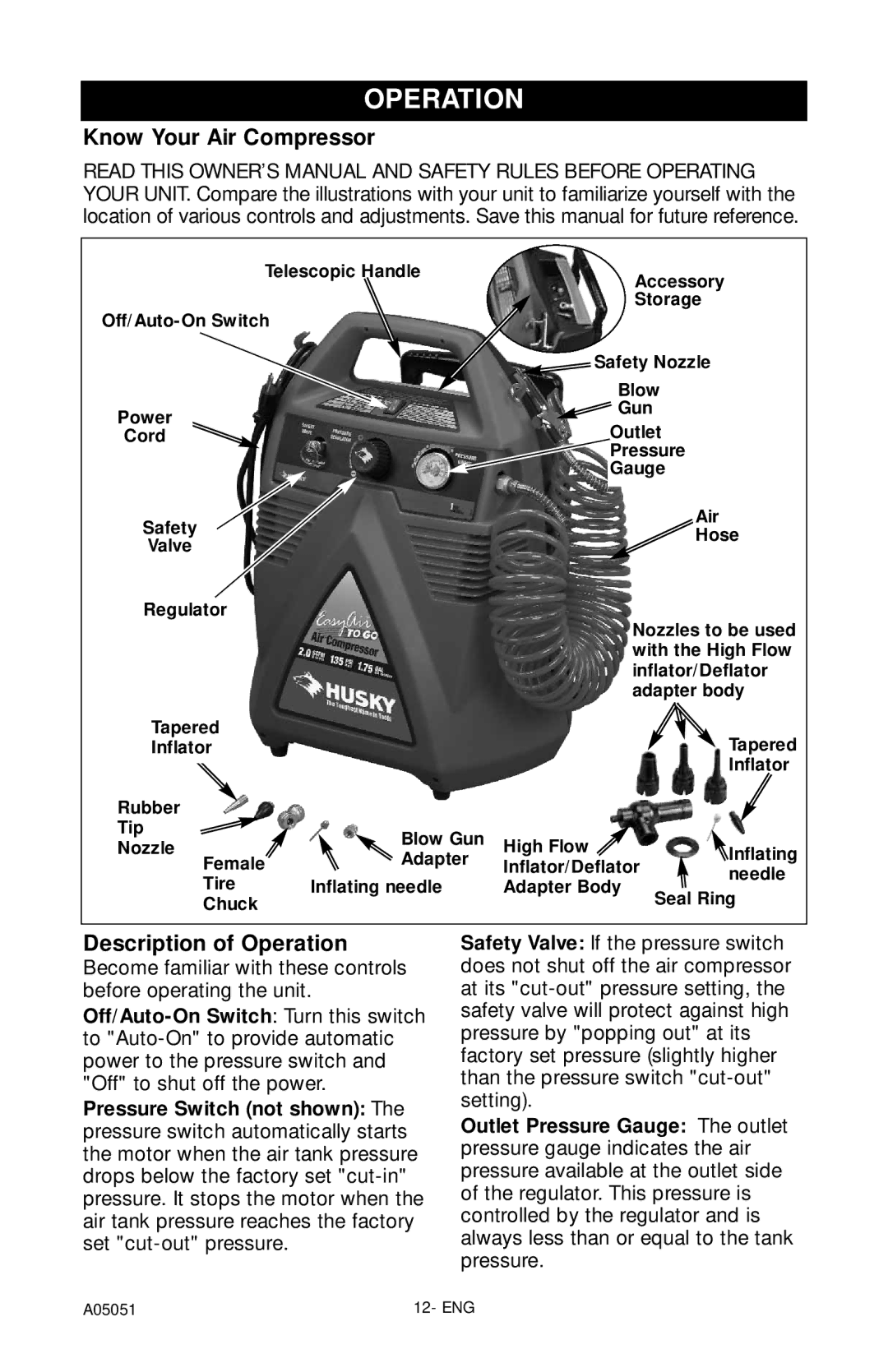
READ THIS OWNER’S MANUAL AND SAFETY RULES BEFORE OPERATING YOUR UNIT. Compare the illustrations with your unit to familiarize yourself with the location of various controls and adjustments. Save this manual for future reference.
Telescopic Handle
Power
Cord
Safety
Valve
Regulator
Tapered
Inflator
Rubber |
| |
Tip | Blow Gun | |
Nozzle | ||
Adapter | ||
Female | ||
Tire | Inflating needle | |
Chuck |
|
Accessory
Storage
![]() Safety Nozzle
Safety Nozzle
Blow
![]() Gun
Gun
Outlet
Pressure
Gauge
|
| Air | |
|
| Hose | |
| Nozzles to be used | ||
| with the High Flow | ||
| inflator/Deflator | ||
| adapter body | ||
|
| Tapered | |
|
| Inflator | |
High Flow |
| Inflating | |
Inflator/Deflator | |||
needle | |||
Adapter Body |
| ||
| Seal Ring | ||
|
| ||
Description of Operation
Become familiar with these controls before operating the unit.
Pressure Switch (not shown): The pressure switch automatically starts the motor when the air tank pressure drops below the factory set
Safety Valve: If the pressure switch does not shut off the air compressor at its
Outlet Pressure Gauge: The outlet pressure gauge indicates the air pressure available at the outlet side of the regulator. This pressure is controlled by the regulator and is always less than or equal to the tank pressure.
A05051 | 12- ENG |
