Fuel system | 3 | |
|
|
|
Remove the throttle cable and fuel hose from the carburettor.
Remove the carburettor.
The carburettor is made by Zama.
Design, function and servicing corre- spond with the Walbro carburettor.
Default carburettor settings:
H = 1 revolution open
L = 1 revolution open
The carburettor needles are fitted with movement limiters (caps).
The carburettor’s design
The carburettor can be divided into three different functional units: the metering unit, the blending unit, and the pump unit.
The metering unit
The needles and the fuel control functions are located here.
The blending unit
Fuel and air are mixed here.
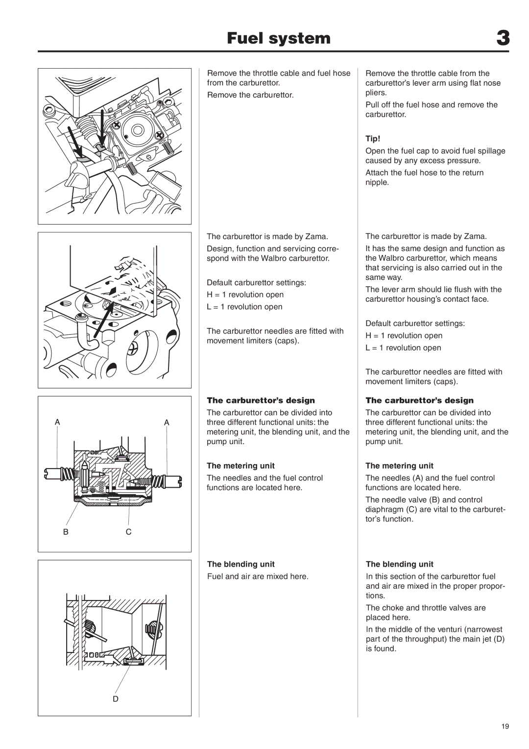
Remove the throttle cable from the carburettor’s lever arm using flat nose pliers.
Pull off the fuel hose and remove the carburettor.
Tip!
Open the fuel cap to avoid fuel spillage caused by any excess pressure.
Attach the fuel hose to the return nipple.
The carburettor is made by Zama.
It has the same design and function as the Walbro carburettor, which means that servicing is also carried out in the same way.
The lever arm should lie flush with the carburettor housing’s contact face.
Default carburettor settings:
H = 1 revolution open
L = 1 revolution open
The carburettor needles are fitted with movement limiters (caps).
The carburettor’s design
The carburettor can be divided into three different functional units: the metering unit, the blending unit, and the pump unit.
The metering unit
The needles (A) and the fuel control functions are located here.
The needle valve (B) and control diaphragm (C) are vital to the carburet- tor’s function.
The blending unit
In this section of the carburettor fuel and air are mixed in the proper propor- tions.
The choke and throttle valves are placed here.
In the middle of the venturi (narrowest part of the throughput) the main jet (D) is found.
19
