Wireless POS Terminal Interface
4.Insert the 24-Volt power cable from the power supply, Hypercom P/N 870003-001, into the terminal transceiver interface receptacle marked Power. Insert the AC power cable from the power supply into an appropriate AC receptacle.
5.Insert the male connector of the 12-foot cable from the terminal transceivers into the female connectors marked Terminal Transceiver 1 or Terminal Transceiver 2 on the terminal transceiver interface.
If the 12-foot cable is not long enough, it may be extended up to 1000 feet by using any four conductor, one-to-one standard telephone extender cable available at various electronic appliance retail outlets.
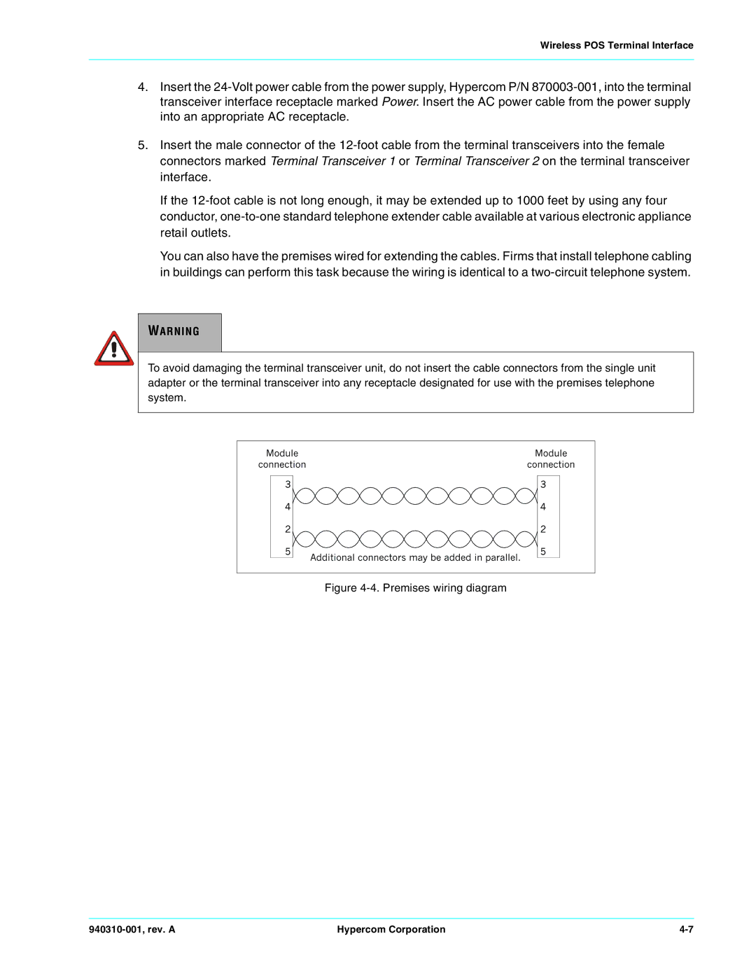
You can also have the premises wired for extending the cables. Firms that install telephone cabling in buildings can perform this task because the wiring is identical to a two-circuit telephone system.
WARNING
To avoid damaging the terminal transceiver unit, do not insert the cable connectors from the single unit adapter or the terminal transceiver into any receptacle designated for use with the premises telephone system.
Figure 4-4. Premises wiring diagram
940310-001, rev. A | Hypercom Corporation | 4-7 |