GMS90X5XC Series | HYUNDAI MicroElectronics |
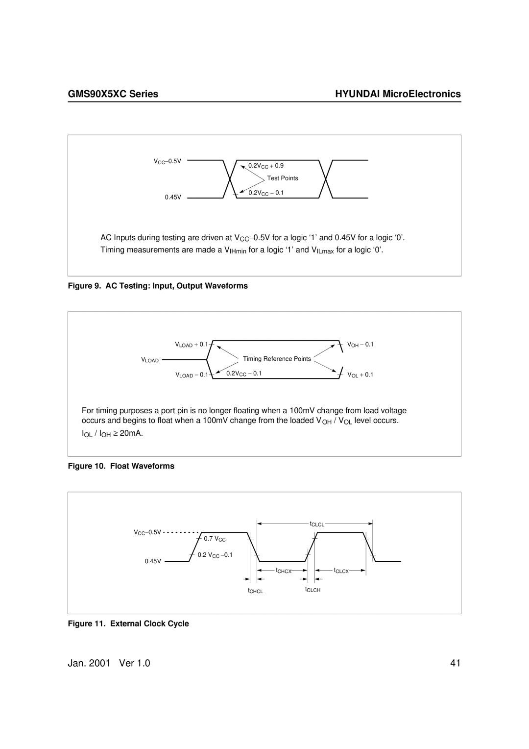
VCC−0.5V ![]()
![]()
![]() 0.2VCC + 0.9
0.2VCC + 0.9
Test Points
0.2VCC − 0.1
0.45V
AC Inputs during testing are driven at VCC−0.5V for a logic ‘1’ and 0.45V for a logic ‘0’. Timing measurements are made a VIHmin for a logic ‘1’ and VILmax for a logic ‘0’.
Figure 9. AC Testing: Input, Output Waveforms
| VLOAD + 0.1 |
|
|
|
|
| VOH − 0.1 | |
VLOAD |
|
| Timing Reference Points |
| ||||
|
|
|
|
| ||||
|
|
|
| |||||
| VLOAD − 0.1 |
|
| 0.2VCC − 0.1 |
|
| VOL + 0.1 | |
|
|
|
| |||||
For timing purposes a port pin is no longer floating when a 100mV change from load voltage occurs and begins to float when a 100mV change from the loaded VOH / VOL level occurs.
IOL / IOH ≥ 20mA.
Figure 10. Float Waveforms
VCC−0.5V
0.7 VCC
0.2 VCC −0.1
0.45V
tCLCL
|
|
|
|
|
|
|
|
|
|
|
|
|
|
|
|
|
|
|
|
|
|
|
|
|
|
|
|
|
|
|
|
|
|
|
|
|
|
|
|
|
|
|
|
|
|
|
|
|
|
|
|
|
|
|
|
|
|
|
|
|
|
|
|
|
|
|
|
|
|
|
|
|
|
|
|
|
|
|
|
|
|
|
|
|
|
|
|
|
|
|
|
| tCHCX |
|
|
|
|
|
|
|
|
|
|
| tCLCX |
|
|
|
|
|
|
|
|
|
|
| |||||||||
|
|
|
|
|
|
|
|
|
|
|
|
|
|
|
|
|
|
|
|
|
|
|
|
|
|
|
|
|
|
|
|
|
|
|
|
tCHCLtCLCH
Figure 11. External Clock Cycle
Jan. 2001 Ver 1.0 | 41 |