HYUNDAI MicroElectronics | GMS90X5XC Series |
X2 MODE
The GMS90X5XC core needs only 6 clock periods per machine cycle. This feature called ”X2” provides the following advantages:
•Divide frequency crystals by 2 (cheaper crystals) while keeping same CPU power.
•Save power consumption while keeping same CPU power (oscillator power saving).
•Save power consumption by dividing dynamically operating frequency by 2 in operating and idle modes.
•Increase CPU power by 2 while keeping same crystal frequency.
In order to keep the original C51 compatibility, a divider by 2 is inserted between the XTAL1 signal and the main clock input of the core (phase generator). This divider may be disabled by software.
X2 Mode Description
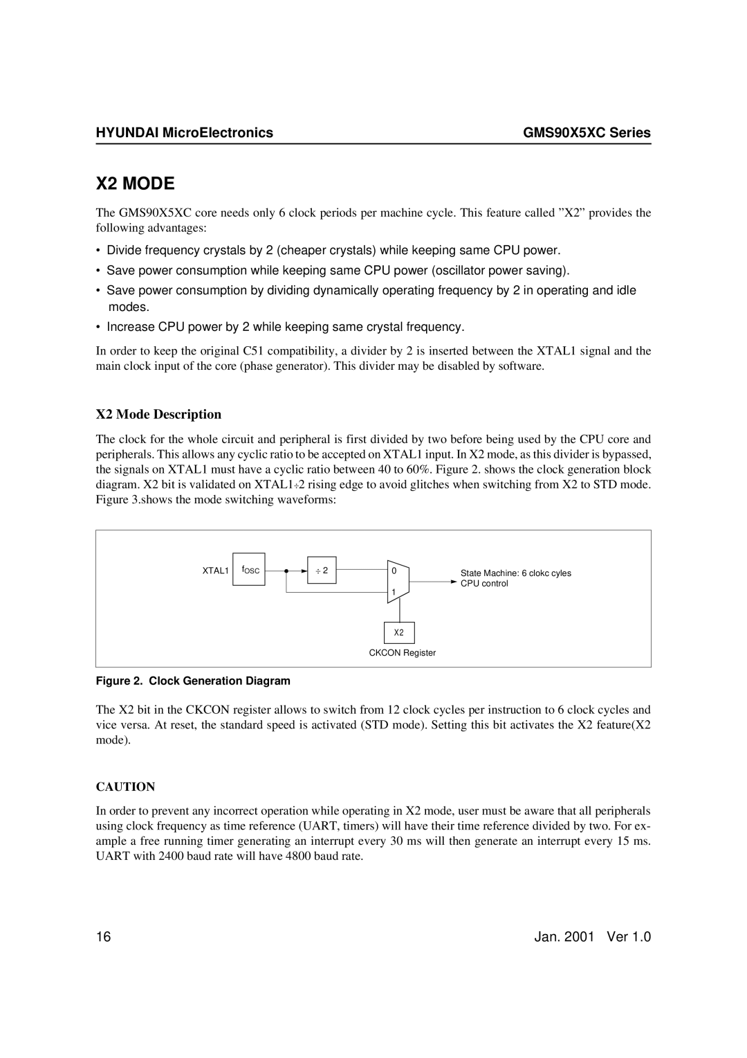
The clock for the whole circuit and peripheral is first divided by two before being used by the CPU core and peripherals. This allows any cyclic ratio to be accepted on XTAL1 input. In X2 mode, as this divider is bypassed, the signals on XTAL1 must have a cyclic ratio between 40 to 60%. Figure 2. shows the clock generation block diagram. X2 bit is validated on XTAL1÷2 rising edge to avoid glitches when switching from X2 to STD mode. Figure 3.shows the mode switching waveforms:
XTAL1 fOSC
÷2
0 |
| State Machine: 6 clokc cyles |
|
| |
1 |
| CPU control |
| ||
|
|
X2
CKCON Register
Figure 2. Clock Generation Diagram
The X2 bit in the CKCON register allows to switch from 12 clock cycles per instruction to 6 clock cycles and vice versa. At reset, the standard speed is activated (STD mode). Setting this bit activates the X2 feature(X2 mode).
CAUTION
In order to prevent any incorrect operation while operating in X2 mode, user must be aware that all peripherals using clock frequency as time reference (UART, timers) will have their time reference divided by two. For ex- ample a free running timer generating an interrupt every 30 ms will then generate an interrupt every 15 ms. UART with 2400 baud rate will have 4800 baud rate.
16 | Jan. 2001 Ver 1.0 |