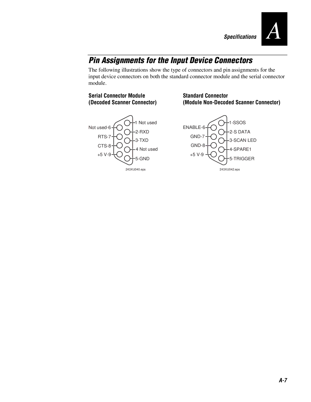
243X specifications
The IBM 243X is part of IBM's OBS (Office of Business Solutions) series, widely recognized for its robust performance and innovative technologies designed for enterprise-level data processing and management. This series is well-suited for organizations demanding reliability, scalability, and efficiency in their operations.One of the standout features of the IBM 243X is its powerful processing capability. It is equipped with advanced multi-core processors that enable it to handle multiple tasks simultaneously, making it ideal for data-intensive applications such as data analysis, transaction processing, and enterprise resource planning (ERP) systems. The architecture of the IBM 243X ensures optimized performance with minimal latency, ensuring that businesses can operate seamlessly even during peak loads.
In terms of memory and storage, the IBM 243X supports a vast amount of RAM and offers flexible storage options. This allows organizations to customize their configurations based on their specific needs. The device can handle large databases and supports fast access speeds, which is vital for real-time data processing. Additionally, IBM’s proprietary storage technologies ensure data integrity and quick retrieval, contributing to overall operational efficiency.
Safety and security are paramount in today’s digital landscape, and the IBM 243X incorporates several advanced security features. With built-in data encryption, secure boot processes, and compliance with international security standards, the IBM 243X safeguards sensitive business information against unauthorized access and potential cyber threats.
Customization and scalability are also key characteristics of the IBM 243X. Organizations can easily scale their infrastructure up or down based on evolving needs. The modular design allows for added components, which can be integrated without disrupting existing operations, ensuring maximum uptime and productivity.
Furthermore, the IBM 243X leverages cloud integration, enabling businesses to seamlessly connect with various cloud services for backup, disaster recovery, and collaborative work environments. This flexibility positions the IBM 243X as a future-proof investment, offering organizations the ability to adapt to changing technological landscapes.
In summary, the IBM 243X stands out with its robust processing capabilities, extensive memory and storage options, advanced security features, and flexibility for customization and scalability. These characteristics make it an invaluable tool for businesses seeking efficiency, reliability, and performance in their operations.

