through a pass through opening in the rear bulkhead on the power supply side of the backpanel, and attached to the SCSI backplane.
SSA disks require the addition of an SSA adapter. To cable internal SSA, a cable assembly is attached to two external ports on the SSA adapter. This runs through a pass through opening in the rear bulkhead on the power supply side of the backpanel and is attached to both ends of the SSA backplane. When using both SSA six-packs, the cable runs to one end of each of the two backplanes with a short SSA cable in between the two backplanes. These configurations provide a loop, which is part of the SSA architecture. The SSA six-pack requires dummy jumper cards in vacant bays to maintain the SSA loop, and so can only support one inch drives. Booting from SSA disks attached to an Advanced SerialRAID adapter (# 6225) is supported from the six-pack or external SSA disks provided that the disks are arranged in a non-RAID configuration.
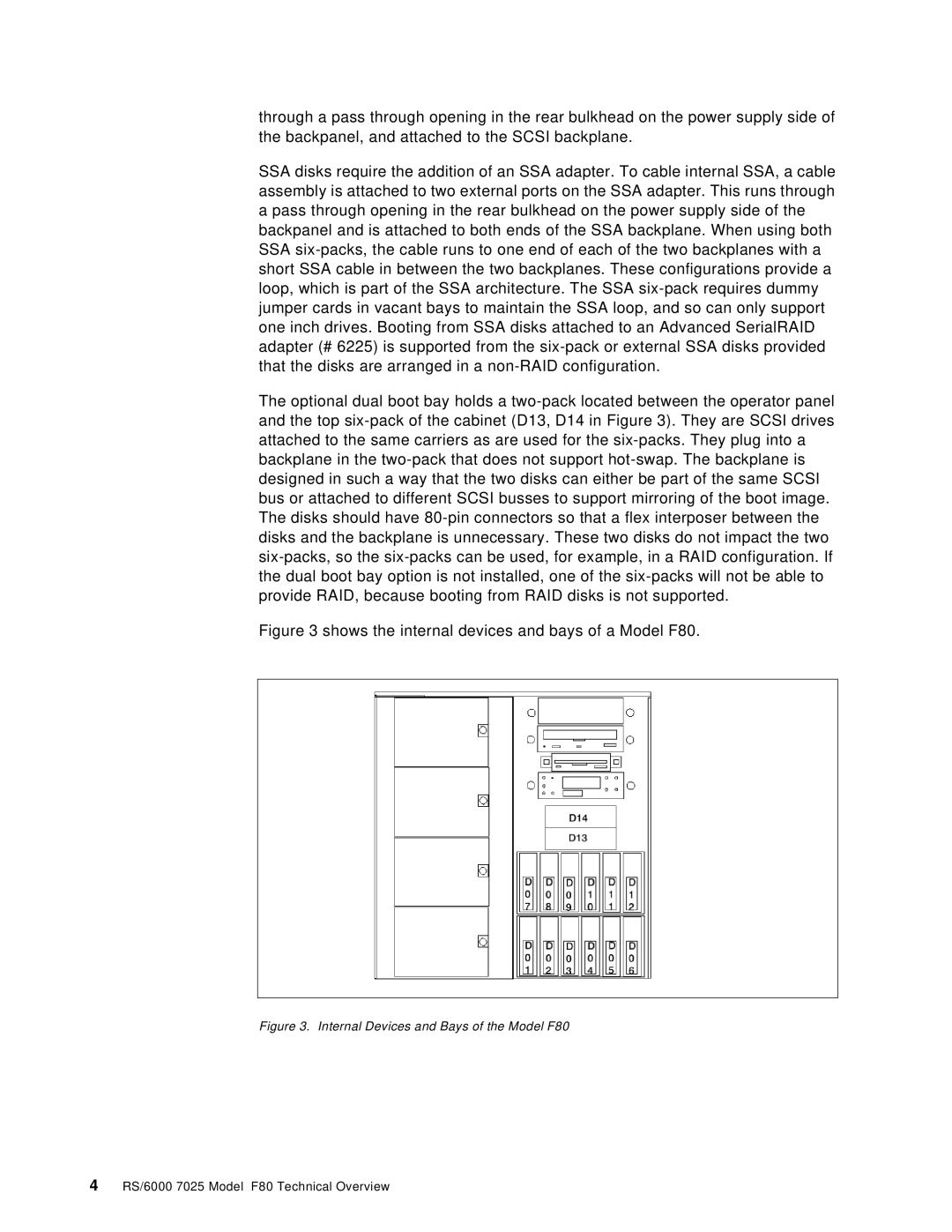
The optional dual boot bay holds a two-pack located between the operator panel and the top six-pack of the cabinet (D13, D14 in Figure 3). They are SCSI drives attached to the same carriers as are used for the six-packs. They plug into a backplane in the two-pack that does not support hot-swap. The backplane is designed in such a way that the two disks can either be part of the same SCSI bus or attached to different SCSI busses to support mirroring of the boot image. The disks should have 80-pin connectors so that a flex interposer between the disks and the backplane is unnecessary. These two disks do not impact the two six-packs, so the six-packs can be used, for example, in a RAID configuration. If the dual boot bay option is not installed, one of the six-packs will not be able to provide RAID, because booting from RAID disks is not supported.
Figure 3 shows the internal devices and bays of a Model F80.
Figure 3. Internal Devices and Bays of the Model F80
4 RS/6000 7025 Model F80 Technical Overview