Internal I/O Architecture
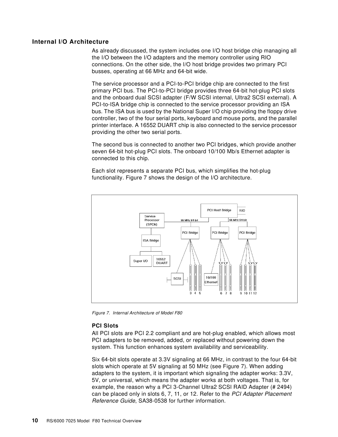
As already discussed, the system includes one I/O host bridge chip managing all the I/O between the I/O adapters and the memory controller using RIO connections. On the other side, the I/O host bridge provides two primary PCI busses, operating at 66 MHz and 64-bit wide.
The service processor and a PCI-to-PCI bridge chip are connected to the first primary PCI bus. The PCI-to-PCI bridge provides three 64-bit hot-plug PCI slots and the onboard dual SCSI adapter (F/W SCSI internal, Ultra2 SCSI external). A PCI-to-ISA bridge chip is connected to the service processor providing an ISA bus. The ISA bus is used by the National Super I/O chip providing the floppy drive controller, two of the four serial ports, keyboard and mouse ports, and the parallel printer interface. A 16552 DUART chip is also connected to the service processor providing the other two serial ports.
The second bus is connected to another two PCI bridges, which provide another seven 64-bit hot-plug PCI slots. The onboard 10/100 Mb/s Ethernet adapter is connected to this chip.
Each slot represents a separate PCI bus, which simplifies the hot-plug functionality. Figure 7 shows the design of the I/O architecture.
Figure 7. Internal Architecture of Model F80
PCI Slots
All PCI slots are PCI 2.2 compliant and are hot-plug enabled, which allows most PCI adapters to be removed, added, or replaced without powering down the system. This function enhances system availability and serviceability.
Six 64-bit slots operate at 3.3V signaling at 66 MHz, in contrast to the four 64-bit slots which operate at 5V signaling at 50 MHz (see Figure 7). When adding adapters to the system, it is important which signaling the adapter works: 3.3V, 5V, or universal, which means the adapter works at both voltages. That is, for example, the reason why a PCI 3-Channel Ultra2 SCSI RAID Adapter (# 2494) can be placed only in slots 6, 7, 11, or 12. Refer to the PCI Adapter Placement Reference Guide, SA38-0538 for further information.

