System Architecture and Technical Overview
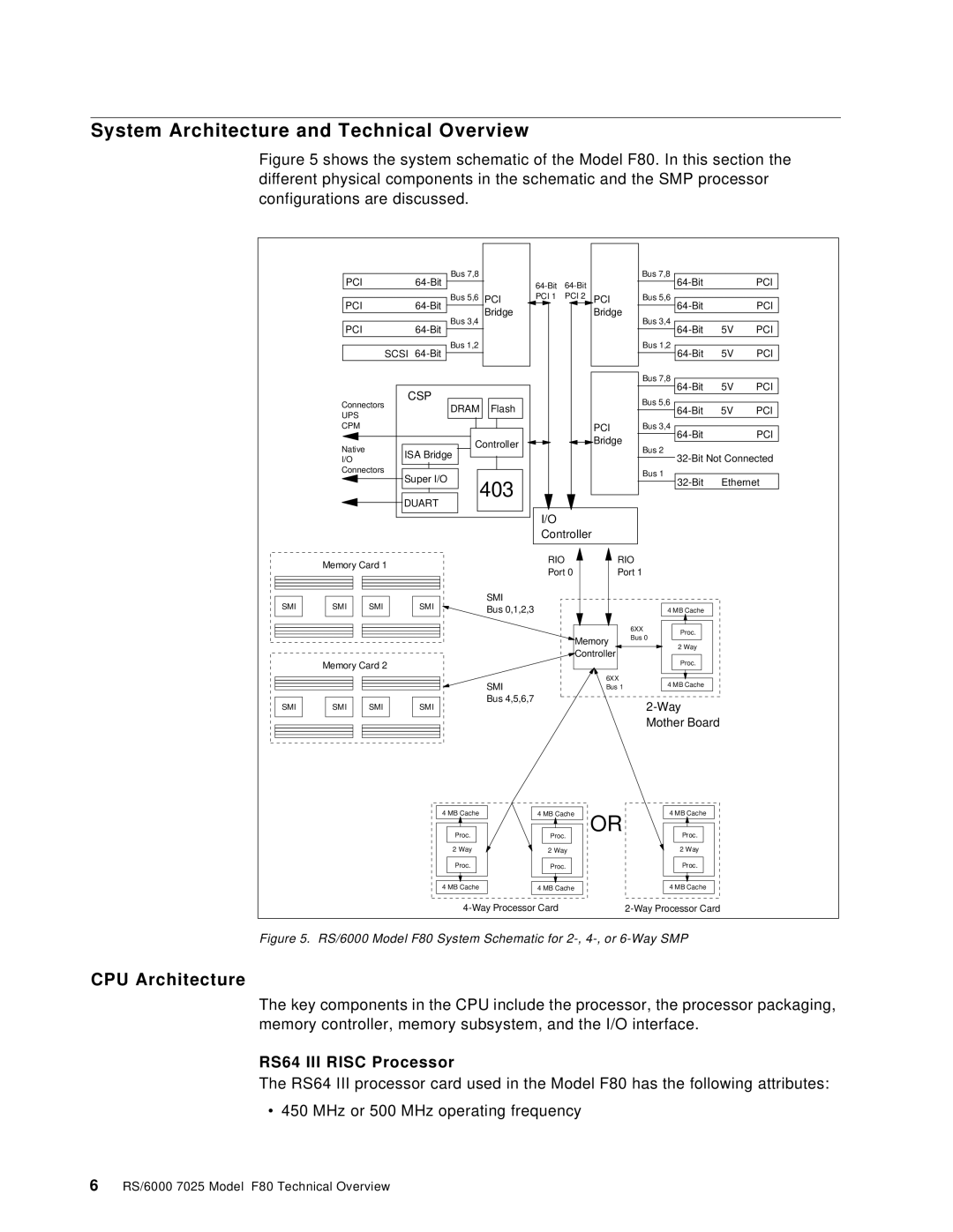
Figure 5 shows the system schematic of the Model F80. In this section the different physical components in the schematic and the SMP processor configurations are discussed.
| PCI |
| Bus 7,8 |
|
|
|
| Bus 7,8 |
| PCI | ||
|
|
|
|
|
|
| ||||||
|
|
|
|
|
|
|
|
|
|
| ||
| PCI |
| Bus 5,6 | PCI | PCI 1 | PCI 2 | PCI | Bus 5,6 |
| PCI | ||
|
|
| Bridge |
|
| Bridge |
|
| ||||
|
|
|
| Bus 3,4 |
|
| Bus 3,4 |
|
|
| ||
| PCI |
|
|
|
|
| 5V | PCI | ||||
|
|
|
|
|
|
|
| |||||
|
| SCSI | Bus 1,2 |
|
|
|
| Bus 1,2 | 5V | PCI | ||
|
|
|
|
|
|
|
| |||||
|
|
|
|
|
|
|
|
| Bus 7,8 | 5V | PCI | |
|
| CSP |
|
|
|
|
|
| ||||
|
|
|
|
|
|
| Bus 5,6 |
|
|
| ||
| Connectors |
| DRAM | Flash |
|
|
| 5V | PCI | |||
|
|
|
|
|
| |||||||
| UPS |
|
|
|
|
|
| |||||
|
|
|
|
|
|
|
|
|
|
|
| |
| CPM |
|
|
|
|
|
| PCI | Bus 3,4 |
| PCI | |
|
|
|
| Controller |
|
| Bridge |
|
| |||
| Native |
|
|
|
| Bus 2 |
|
|
| |||
|
|
|
|
|
|
|
|
| ||||
| ISA Bridge |
|
|
|
| |||||||
| I/O |
|
|
|
|
| ||||||
|
|
|
|
|
|
|
|
| ||||
| Connectors |
|
|
|
|
|
| Bus 1 |
|
|
| |
|
| Super I/O | 403 |
|
|
| Ethernet | |||||
|
|
|
|
|
| |||||||
|
|
|
|
|
|
|
| |||||
|
| DUART |
|
|
|
|
|
|
| |||
|
|
|
|
|
|
|
|
|
|
| ||
|
|
|
|
|
| I/O |
|
|
|
|
|
|
|
|
|
|
|
| Controller |
|
|
|
| ||
| Memory Card 1 |
|
|
| RIO |
| RIO |
|
|
| ||
|
|
|
| Port 0 | Port 1 |
|
|
| ||||
|
|
|
|
|
|
|
|
| ||||
SMI | SMI | SMI | SMI |
| SMI |
|
|
|
|
|
|
|
| Bus 0,1,2,3 |
|
|
| 4 MB Cache |
|
| |||||
|
|
|
|
|
|
|
|
| 6XX | Proc. |
|
|
|
|
|
|
|
|
| Memory | Bus 0 |
|
| ||
|
|
|
|
|
|
|
|
|
| |||
|
|
|
|
|
|
|
| 2 Way |
|
| ||
|
|
|
|
|
|
| Controller |
|
|
| ||
|
|
|
|
|
|
|
|
|
|
| ||
| Memory Card 2 |
|
|
|
|
|
|
| Proc. |
|
| |
|
|
|
|
|
|
|
|
|
|
| ||
|
|
|
|
| SMI |
|
| 6XX | 4 MB Cache |
|
| |
|
|
|
|
|
|
| Bus 1 |
|
| |||
SMI | SMI | SMI | SMI |
| Bus 4,5,6,7 |
|
|
|
|
| ||
|
|
|
|
|
|
| ||||||
|
|
|
|
|
|
|
|
| Mother Board |
|
| |
|
|
| 4 MB Cache |
| 4 MB Cache | OR | 4 MB Cache |
|
| |||
|
|
|
| Proc. |
| Proc. |
|
| Proc. |
|
| |
|
|
|
| 2 Way |
| 2 Way |
|
| 2 Way |
|
| |
|
|
|
| Proc. |
| Proc. |
|
| Proc. |
|
| |
|
|
| 4 MB Cache |
| 4 MB Cache |
| 4 MB Cache |
|
| |||
|
|
|
|
|
|
|
| |||||
Figure 5. | RS/6000 Model F80 System Schematic for |
|
| |||||||||
CPU Architecture
The key components in the CPU include the processor, the processor packaging, memory controller, memory subsystem, and the I/O interface.
RS64 III RISC Processor
The RS64 III processor card used in the Model F80 has the following attributes:
• 450 MHz or 500 MHz operating frequency
