Removing and replacing a FRU
2
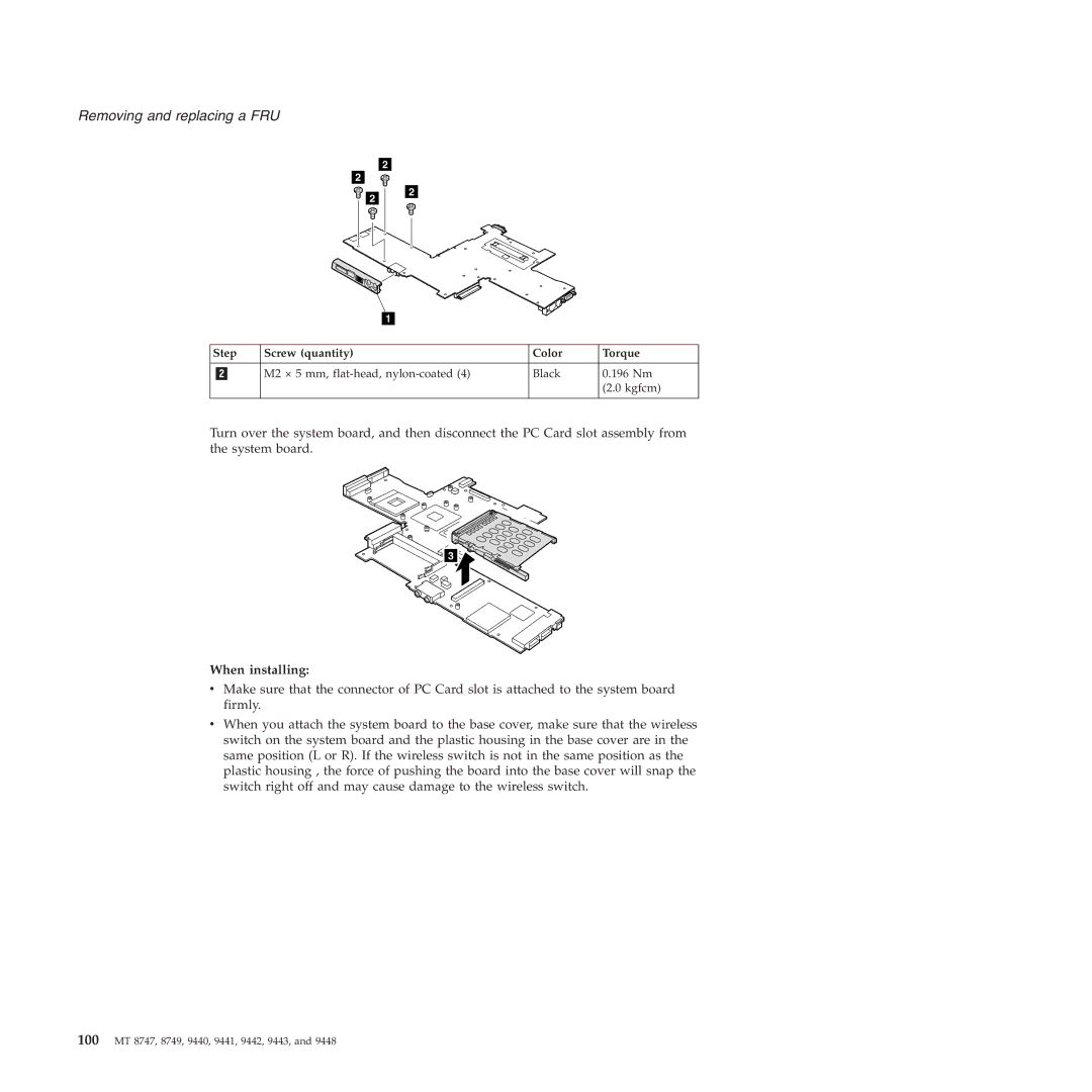
Step | Screw (quantity) | Color | Torque |
|
|
|
|
| M2 × 5 mm, | Black | 0.196 Nm |
|
|
| (2.0 kgfcm) |
|
|
|
|
Turn over the system board, and then disconnect the PC Card slot assembly from the system board.
3 ![]()
When installing:
vMake sure that the connector of PC Card slot is attached to the system board firmly.
vWhen you attach the system board to the base cover, make sure that the wireless switch on the system board and the plastic housing in the base cover are in the same position (L or R). If the wireless switch is not in the same position as the plastic housing , the force of pushing the board into the base cover will snap the switch right off and may cause damage to the wireless switch.