Module for IBM BladeCenter
Installation Guide
Nortel 10 Gigabit Uplink Ethernet Switch
Page
Module for IBM BladeCenter
First Edition May
Chapter 2. Installing and removing the GbE switch module
Contents
Safety
Chapter 3. Installing and removing options
Appendix A. IBM Statement of Limited Warranty Z125-4753-08 04/2004
Chapter 7. Parts listing
Chapter 8. Solving problems
Chapter 6. Updating the software
Safety
vi Nortel 10 Gigabit Uplink Ethernet Switch Module Installation Guide
Antes de instalar este produto, leia as Informações sobre Segurança
Statement DANGER
To avoid a shock hazard
Page
Product name and serial number label
Chapter 1. Introduction
Media access control MAC address label
v Safety Information
Specifications
Media access control MAC address
Related documentation
v IBM BladeCenter Management Module Command Line Reference Guide
Notices and statements used in this document
4 TX/RX XFP port
Major components of the GbE switch module
Information panel RS232 serial console port CX4 ports Release latch
SFP port
CX 4 port
Information panel overview
RS232 serial port
XFP module
LEDs
TX/RX
Chapter 1. Introducing the Gigabit Ethernet switch module
8 Nortel 10 Gigabit Uplink Ethernet Switch Module Installation Guide
Chapter 2. Installing and removing the GbE switch module
Installation guidelines
Handling static-sensitive devices
Installing the GbE switch module
System reliability considerations
6. Remove the GbE switch module from its static-protective package
Removing the GbE switch module
12 Nortel 10 Gigabit Uplink Ethernet Switch Module Installation Guide
Chapter 2. Installing and removing the GbE switch module
14 Nortel 10 Gigabit Uplink Ethernet Switch Module Installation Guide
Statement
Chapter 3. Installing and removing options
Handling an XFP or SFP module
Class 1 Laser Product Laser Klasse Laser Klass Luokan 1 Laserlaite `
Installing an XFP module
DANGER
Appareil A Laser de Classe
TX/RX
Chapter 3. Installing and removing options
LINK
Wire tab Protective cap XFP module
Installing an SFP module
Removing an XFP module
Removing an SFP module
SFP module
20 Nortel 10 Gigabit Uplink Ethernet Switch Module Installation Guide
Connecting the CX4 module cable
Connecting the serial console cable
Disconnecting the serial console cable
Chapter 4. Cabling
Disconnecting a CX4 module cable
Connecting an XFP module cable
1. Remove the protective caps from the end of the fiber-optic cable
Disconnecting an SFP module cable
Disconnecting the XFP module cable
Connecting the SFP module cable
Chapter 5. Configuring the GbE switch module
26 Nortel 10 Gigabit Uplink Ethernet Switch Module Installation Guide
Establishing a TCP/IP session using the management module
2. From the I/O Module Tasks menu, click Configuration
External management
Configuring the GbE switch module using Telnet
Enabling management over external ports
External ports
Configuring the GbE switch module using the serial-port interface
Connecting to the GbE switch module
Accessing the main menu
v 9600 baud v 8 data bits v No parity v 1 stop bit v No flow control
Initial configuration
Logging in to the GbE switch module
Chapter 6. Updating the software
Determining the level of GbE switch module software
Obtaining the latest level of switch software
3. Locate the I/O Module Firmware VPD section
Upgrading the GbE switch module software
Resetting and restarting the GbE switch module
3. Click Power Off Modules
36 Nortel 10 Gigabit Uplink Ethernet Switch Module Installation Guide
Chapter 7. Parts listing
38 Nortel 10 Gigabit Uplink Ethernet Switch Module Installation Guide
Running POST
Chapter 8. Solving problems
POST errors
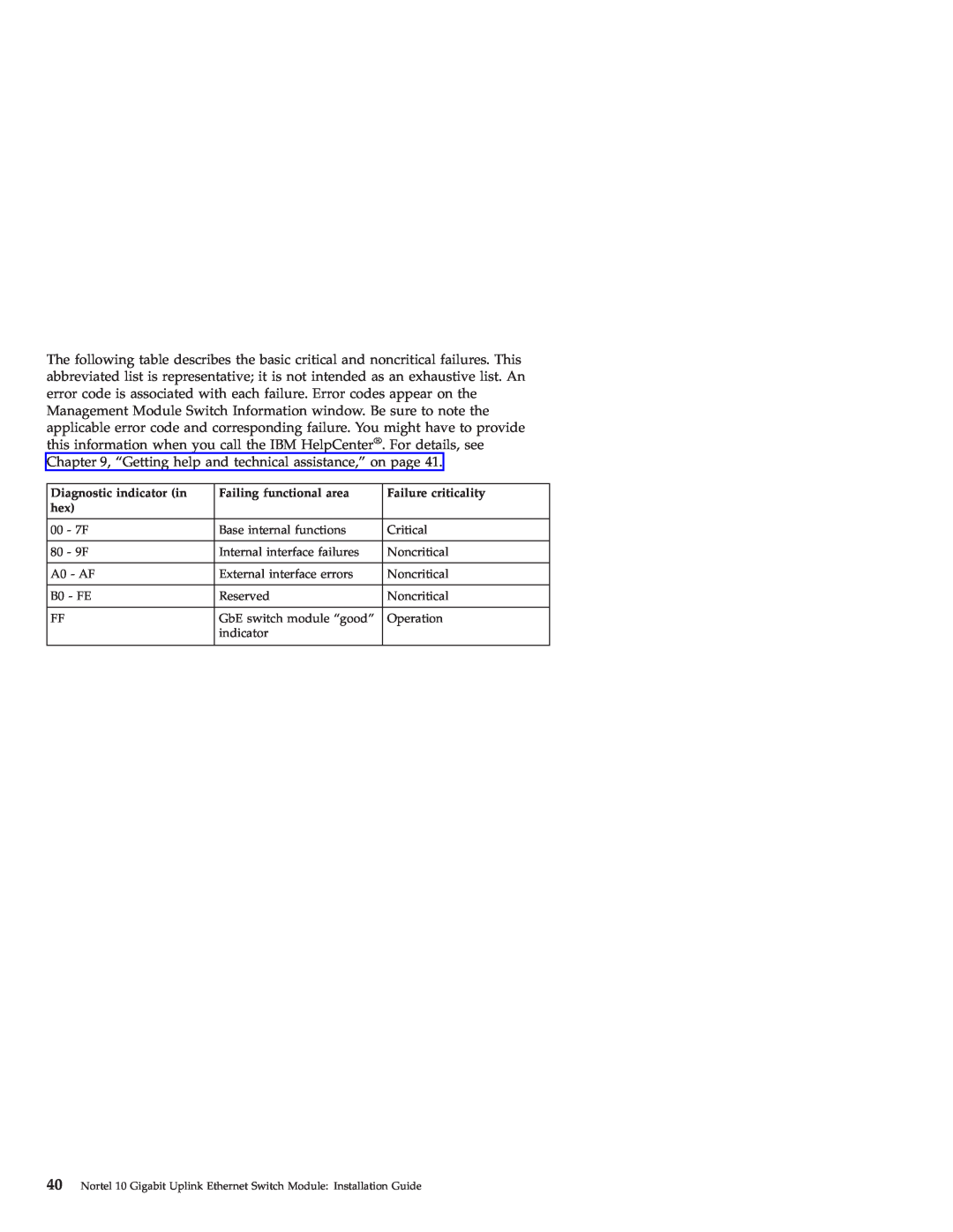
Failing functional area
Diagnostic indicator in
40 Nortel 10 Gigabit Uplink Ethernet Switch Module Installation Guide
Failure criticality
Before you call
Using the documentation
Chapter 9. Getting help and technical assistance
Getting help and information from the World Wide Web
Software service and support
Hardware service and support
42 Nortel 10 Gigabit Uplink Ethernet Switch Module Installation Guide
What this Warranty Does not Cover
Appendix A. IBM Statement of Limited Warranty Z125-4753-08 04/2004
What this Warranty Covers
Part 1 - General Terms
How to Obtain Warranty Service
What IBM Will Do to Correct Problems
Exchange of a Machine or Part
Your Additional Responsibilities
Limitation of Liability
Governing Law
AMERICAS ARGENTINA
Part 2 - Country-unique Terms
Jurisdiction
Jurisdiction The following is added after the first sentence
MEXICO
COLOMBIA
EQUADOR
PARAGUAY
Limitation of Liability The following replaces item 1 of this section
NORTH AMERICA
CANADA
UNITED STATES
Arbitration The following is added under this heading
CAMBODIA AND LAOS
CAMBODIA, INDONESIA, AND LAOS
HONG KONG S.A.R. OF CHINA AND MACAU S.A.R. OF CHINA
MALAYSIA
JAPAN
Governing Law The following sentence is added to this section
PHILIPPINES
NEW ZEALAND
PEOPLE’S REPUBLIC OF CHINA PRC
THE FOLLOWING TERMS APPLY TO ALL EMEA COUNTRIES
SINGAPORE
EUROPE, MIDDLE EAST, AFRICA EMEA
54 Nortel 10 Gigabit Uplink Ethernet Switch Module Installation Guide
1 “the laws of Austria” in Albania, Armenia, Azerbaijan, Belarus
Jurisdiction The following exceptions are added to this section
Cameroon, Cape Verde, Central African Republic, Chad, Comoros, Congo Republic, Djibouti, Democratic Republic of Congo, Equatorial Guinea, French Guiana, French Polynesia, Gabon, Gambia, Guinea, Guinea-Bissau, Ivory Coast, Lebanon, Madagascar, Mali, Mauritania, Mauritius, Mayotte, Morocco, New Caledonia, Niger, Reunion, Senegal, Seychelles, Togo, Tunisia, Vanuatu, and Wallis & Futuna all disputes arising out of this Statement of Limited Warranty or related to its violation or execution, including summary proceedings, will be settled exclusively by the Commercial Court of Paris 5 in Russia, all disputes arising out of or in relation to the interpretation, the violation, the termination, the nullity of the execution of this Statement of Limited Warranty shall be settled by Arbitration Court of Moscow 6 in South Africa, Namibia, Lesotho and Swaziland, both of us agree to submit all disputes relating to this Statement of Limited Warranty to the jurisdiction of the High Court in Johannesburg 7 in Turkey all disputes arising out of or in connection with this Statement of Limited Warranty shall be resolved by the Istanbul Central Sultanahmet Courts and Execution Directorates of Istanbul, the Republic of Turkey 8 in each of the following specified countries, any legal claim arising out of this Statement of Limited Warranty will be brought before, and settled exclusively by, the competent court of a Athens for Greece
THE FOLLOWING TERMS APPLY TO ALL EU COUNTRIES
How to Obtain Warranty Service The following is added to this section
EUROPEAN UNION EU
CONSUMERS
FRANCE AND BELGIUM
THE FOLLOWING TERMS APPLY TO THE COUNTRY SPECIFIED AUSTRIA
The following sentence is added to the end of item
The following paragraphs are added to this section
The second paragraph does not apply
EGYPT
GERMANY
HUNGARY
Items for Which IBM is Not Liable
What this Warranty Covers The following is added to this section
IRELAND
UNITED KINGDOM
SLOVAKIA
SOUTH AFRICA, NAMIBIA, BOTSWANA, LESOTHO AND SWAZILAND
Nortel 10 Gigabit Uplink Ethernet Switch Module for IBM BladeCenter
Part 3 - Warranty Information
Warranty Period
Types of Warranty Service
3. Courier or Depot Service
1. Customer Replaceable Unit “CRU” Service
2. On-site Service
4. Customer Carry-In or Mail-In Service
7. CRU and Customer Carry-In or Mail-In Service
EU Country Telephone List
Appendix A. IBM Statement of Limited Warranty Z125-4753-08 04/2004
Italy -- +39-800-820-094
66 Nortel 10 Gigabit Uplink Ethernet Switch Module Installation Guide
Armonk, NY U.S.A
Appendix B. Notices
IBM Director of Licensing IBM Corporation North Castle Drive
Trademarks
Appendix B. Notices
Important notes
Product recycling and disposal
70 Nortel 10 Gigabit Uplink Ethernet Switch Module Installation Guide
Federal Communications Commission FCC statement
Battery return program
Electronic emission notices
Australia and New Zealand Class A statement
United Kingdom telecommunications safety requirement
Industry Canada Class A emission compliance statement
European Union EMC Directive conformance statement
Taiwanese Class A warning statement Chinese Class A warning statement
Japanese Voluntary Control Council for Interference VCCI statement
74 Nortel 10 Gigabit Uplink Ethernet Switch Module Installation Guide
Index A
76 Nortel 10 Gigabit Uplink Ethernet Switch Module Installation Guide
Index
78 Nortel 10 Gigabit Uplink Ethernet Switch Module Installation Guide
Page
1P P/N 31R1719