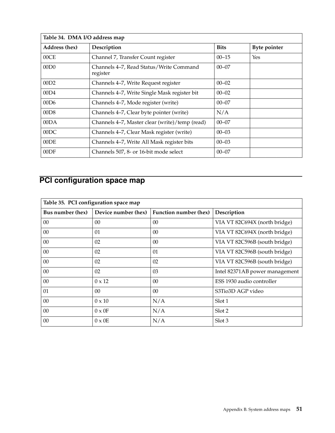
Table 34. DMA I/O address map |
|
| |
|
|
|
|
Address (hex) | Description | Bits | Byte pointer |
|
|
|
|
00CE | Channel 7, Transfer Count register | Yes | |
|
|
|
|
00D0 | Channels |
| |
| register |
|
|
|
|
|
|
00D2 | Channels |
| |
|
|
|
|
00D4 | Channels |
| |
|
|
|
|
00D6 | Channels |
| |
|
|
|
|
00D8 | Channels | N/A |
|
|
|
|
|
00DA | Channels |
| |
|
|
|
|
00DC | Channels |
| |
|
|
|
|
00DE | Channels |
| |
|
|
|
|
00DF | Channels 507, 8- or |
| |
|
|
|
|
PCI configuration space map |
|
| ||
|
|
|
|
|
| Table 35. PCI configuration space map |
|
| |
|
|
|
|
|
| Bus number (hex) | Device number (hex) | Function number (hex) | Description |
|
|
|
|
|
| 00 | 00 | 00 | VIA VT 82C694X (north bridge) |
|
|
|
|
|
| 00 | 01 | 00 | VIA VT 82C694X (north bridge) |
|
|
|
|
|
| 00 | 02 | 00 | VIA VT 82C596B (south bridge) |
|
|
|
|
|
| 00 | 02 | 01 | VIA VT 82C596B (south bridge) |
|
|
|
|
|
| 00 | 02 | 02 | VIA VT 82C596B (south bridge) |
|
|
|
|
|
| 00 | 02 | 03 | Intel 82371AB power management |
|
|
|
|
|
| 00 | 0 x 12 | 00 | ESS 1930 audio controller |
|
|
|
|
|
| 01 | 00 | 00 | S3Tio3D AGP video |
|
|
|
|
|
| 00 | 0 x 10 | N/A | Slot 1 |
|
|
|
|
|
| 00 | 0 x 0F | N/A | Slot 2 |
|
|
|
|
|
| 00 | 0 x 0E | N/A | Slot 3 |
|
|
|
|
|
Appendix B. System address maps 51