Chapter 4. Power supply
A
•System board
•Adapters
•Internal drives
•Keyboard and auxiliary devices
•USB devices
A logic signal on the power connector controls the power supply; the front panel switch is not directly connected to the power supply.
The power supply connects to the system board with a 2 x 10 pin connector.
Power input
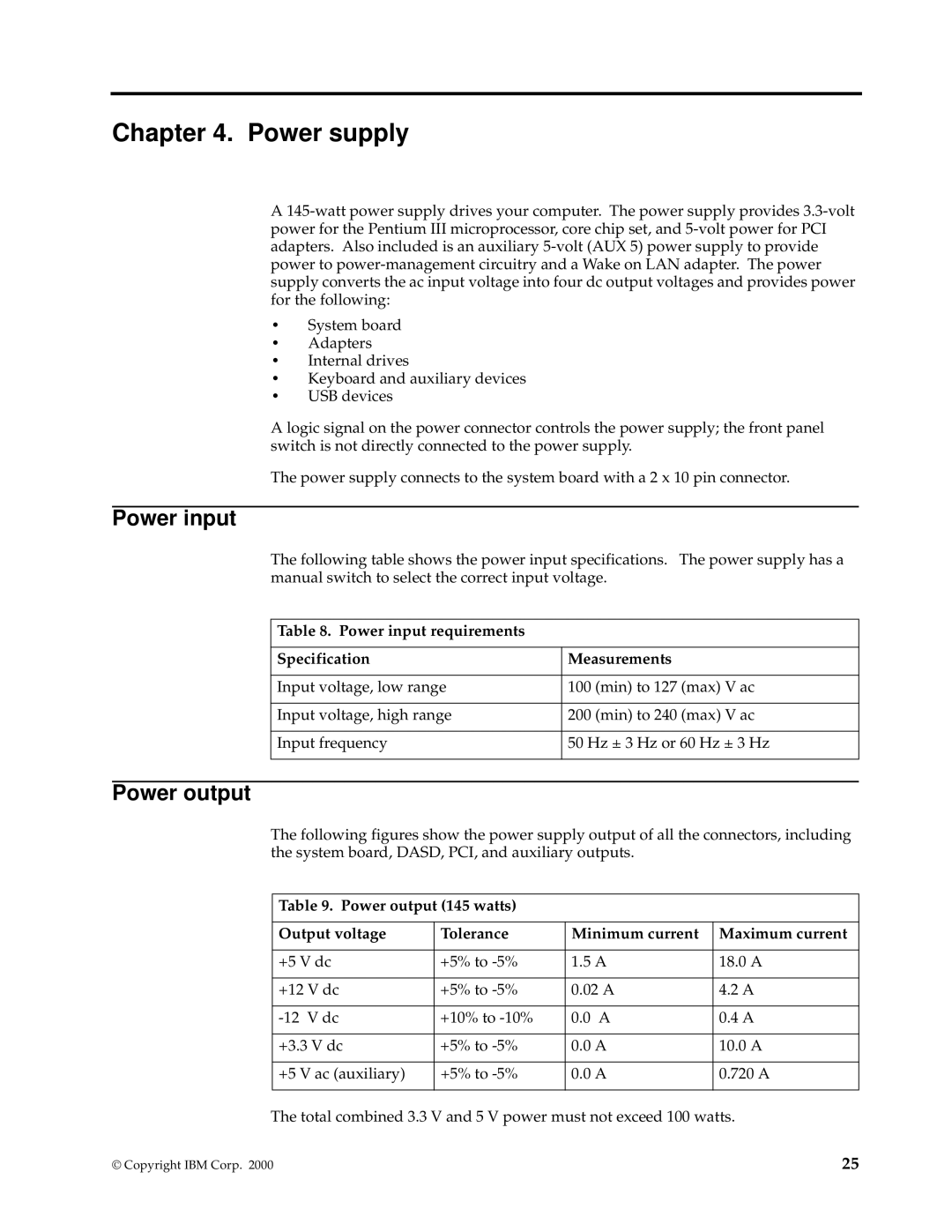
The following table shows the power input specifications. The power supply has a manual switch to select the correct input voltage.
Table 8. Power input requirements
Specification | Measurements |
|
|
Input voltage, low range | 100 (min) to 127 (max) V ac |
|
|
Input voltage, high range | 200 (min) to 240 (max) V ac |
|
|
Input frequency | 50 Hz ± 3 Hz or 60 Hz ± 3 Hz |
|
|
Power output
The following figures show the power supply output of all the connectors, including the system board, DASD, PCI, and auxiliary outputs.
Table 9. Power output (145 watts)
Output voltage | Tolerance | Minimum current | Maximum current |
|
|
|
|
+5 V dc | +5% to | 1.5 A | 18.0 A |
|
|
|
|
+12 V dc | +5% to | 0.02 A | 4.2 A |
|
|
|
|
+10% to | 0.0 A | 0.4 A | |
|
|
|
|
+3.3 V dc | +5% to | 0.0 A | 10.0 A |
|
|
|
|
+5 V ac (auxiliary) | +5% to | 0.0 A | 0.720 A |
|
|
|
|
The total combined 3.3 V and 5 V power must not exceed 100 watts.
© Copyright IBM Corp. 2000 | 25 |
