Appendix A. Connector pin assignments
The following figures show the pin assignments for various system board connectors.
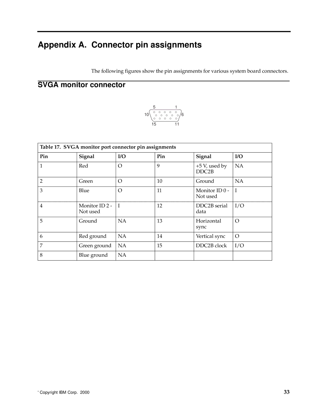
SVGA monitor connector
51
10 ![]() 6
6
15 11
Table 17. SVGA monitor port connector pin assignments
Pin | Signal | I/O | Pin | Signal | I/O |
|
|
|
|
|
|
1 | Red | O | 9 | +5 V, used by | NA |
|
|
|
| DDC2B |
|
|
|
|
|
|
|
2 | Green | O | 10 | Ground | NA |
|
|
|
|
|
|
3 | Blue | O | 11 | Monitor ID 0 - | I |
|
|
|
| Not used |
|
|
|
|
|
|
|
4 | Monitor ID 2 - | I | 12 | DDC2B serial | I/O |
| Not used |
|
| data |
|
|
|
|
|
|
|
5 | Ground | NA | 13 | Horizontal | O |
|
|
|
| sync |
|
|
|
|
|
|
|
6 | Red ground | NA | 14 | Vertical sync | O |
|
|
|
|
|
|
7 | Green ground | NA | 15 | DDC2B clock | I/O |
|
|
|
|
|
|
8 | Blue ground | NA |
|
|
|
|
|
|
|
|
|
© Copyright IBM Corp. 2000 | 33 |