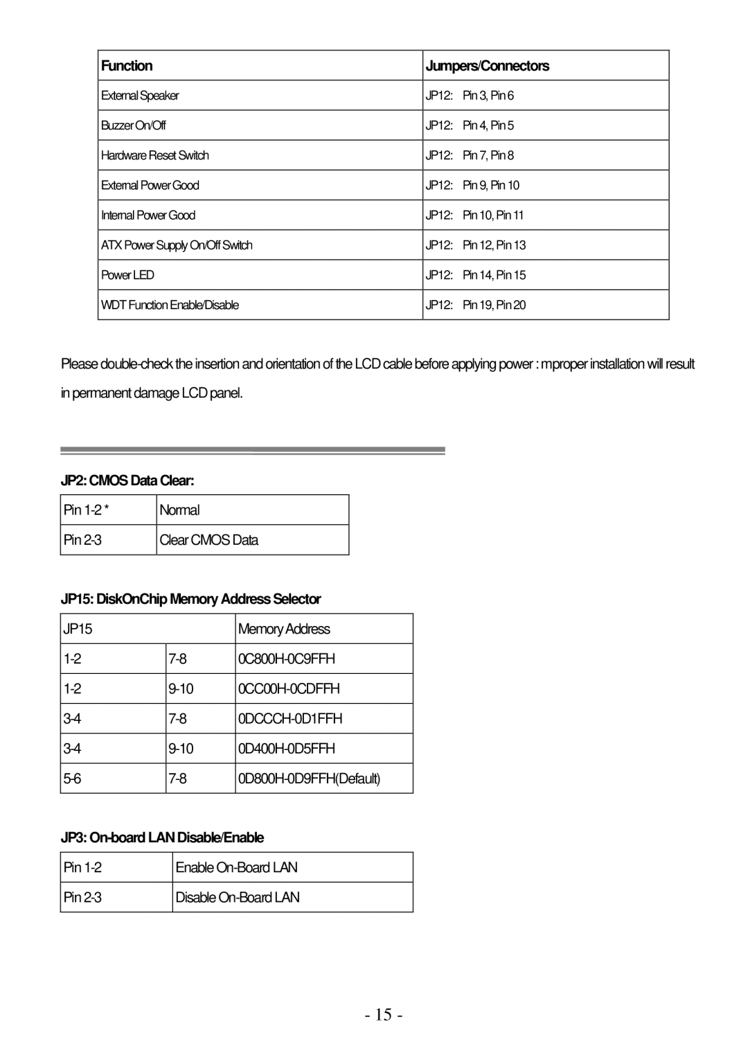
Function | Jumpers/Connectors | |
|
|
|
External Speaker | JP12: | Pin 3, Pin 6 |
|
|
|
Buzzer On/Off | JP12: | Pin 4, Pin 5 |
|
|
|
Hardware Reset Switch | JP12: | Pin 7, Pin 8 |
|
|
|
External Power Good | JP12: | Pin 9, Pin 10 |
|
| |
Internal Power Good | JP12: Pin 10, Pin 11 | |
|
|
|
ATX Power Supply On/Off Switch | JP12: | Pin 12, Pin 13 |
|
|
|
Power LED | JP12: | Pin 14, Pin 15 |
|
|
|
WDT Function Enable/Disable | JP12: | Pin 19, Pin 20 |
|
|
|
Please
JP2: CMOS Data Clear:
Pin | Normal |
|
| |
|
|
|
|
|
Pin | Clear CMOS Data |
| ||
|
|
|
|
|
JP15: DiskOnChip Memory Address Selector | ||||
|
|
|
| |
JP15 |
|
| MemoryAddress | |
|
|
|
| |
| ||||
|
|
|
| |
| ||||
|
|
|
| |
| ||||
|
|
|
| |
| ||||
|
|
|
| |
| ||||
|
|
|
|
|
JP3: On-board LAN Disable/Enable
Pin | Enable |
|
|
Pin | Disable |
|
|
- 15 -