FDTD codes use periodic boundary conditions. Fields leaving through one side will magically reappear coming from the other, which may lead to divergences if you don’t put in absorbers of some sort. Sloppy absorber design may lead to fields travelling many, many periods, leading to anomalously slow convergence. Figure 2.4 is an example of a divergence due to PMLs used with plane wave sources. Note that the divergence looks
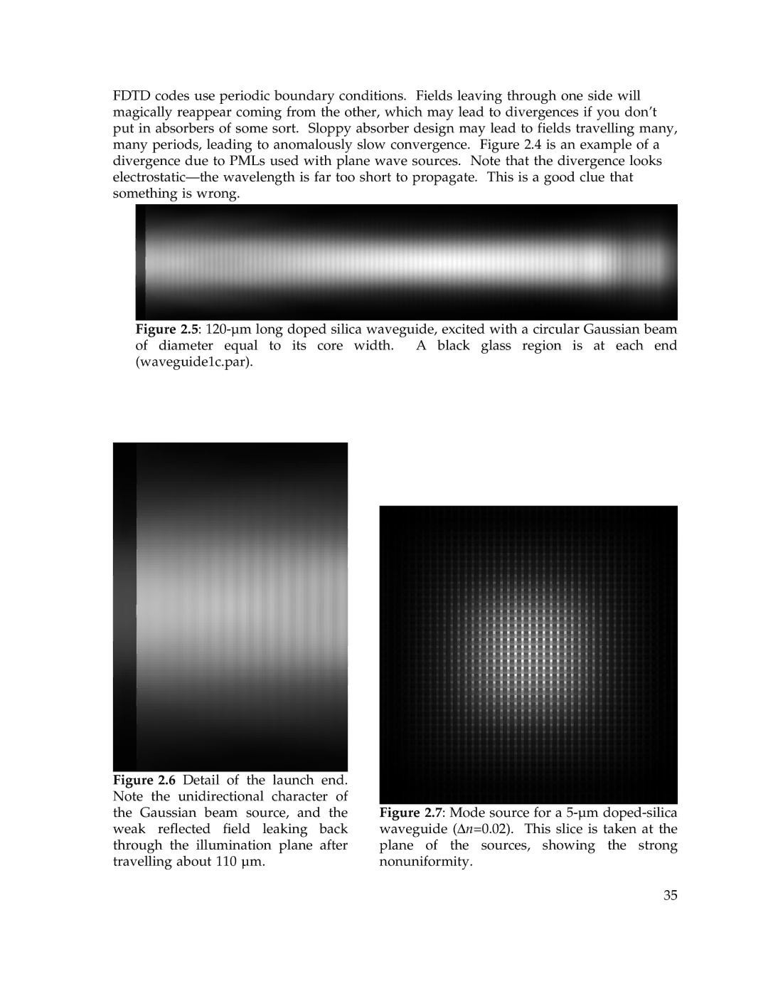
Figure 2.5: 120-µm long doped silica waveguide, excited with a circular Gaussian beam of diameter equal to its core width. A black glass region is at each end (waveguide1c.par).
Figure 2.6 Detail of the launch end. Note the unidirectional character of the Gaussian beam source, and the weak reflected field leaking back through the illumination plane after travelling about 110 µm.
Figure 2.7: Mode source for a 5-µm doped-silica waveguide (Δn=0.02). This slice is taken at the plane of the sources, showing the strong nonuniformity.
35
