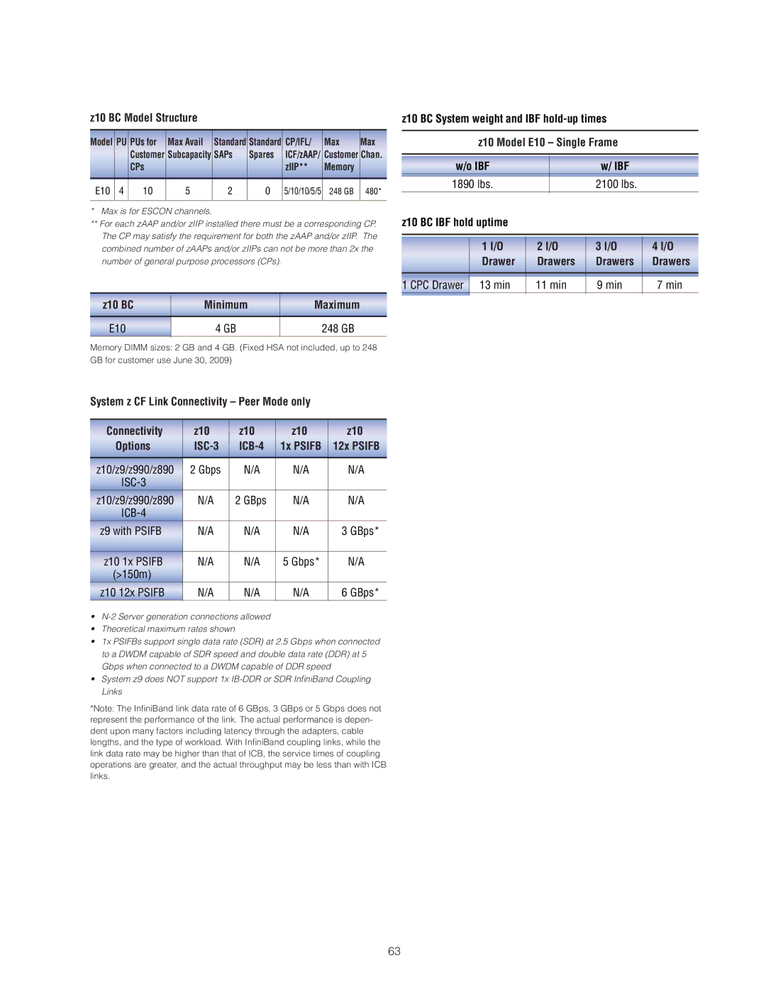
z10 BC Model Structure
Model | PU | PUs for | Max Avail | Standard | Standard | CP/IFL/ | Max | Max |
|
| Customer | Subcapacity | SAPs | Spares | ICF/zAAP/ | Customer | Chan. |
|
| CPs |
|
|
| zIIP** | Memory |
|
|
|
|
|
|
|
|
|
|
E10 | 4 | 10 | 5 | 2 | 0 | 5/10/10/5/5 | 248 GB | 480* |
|
|
|
|
|
|
|
|
|
*Max is for ESCON channels.
**For each zAAP and/or zIIP installed there must be a corresponding CP. The CP may satisfy the requirement for both the zAAP and/or zIIP. The combined number of zAAPs and/or zIIPs can not be more than 2x the number of general purpose processors (CPs).
z10 BC | Minimum | Maximum |
|
|
|
E10 | 4 GB | 248 GB |
Memory DIMM sizes: 2 GB and 4 GB. (Fixed HSA not included, up to 248 GB for customer use June 30, 2009)
z10 | BC System weight and IBF |
| ||||
|
|
|
| |||
|
| z10 Model E10 – Single Frame |
| |||
|
|
|
|
|
|
|
| w/o IBF |
|
| w/ IBF |
| |
| 1890 lbs. |
|
| 2100 lbs. |
| |
z10 | BC IBF hold uptime |
|
|
|
| |
|
|
|
|
|
|
|
|
|
|
|
|
|
|
|
| 1 I/O | 2 I/O | 3 I/O | 4 I/O | |
|
| Drawer | Drawers | Drawers | Drawers | |
|
|
|
|
|
| |
1 CPC Drawer | 13 min | 11 min | 9 min | 7 min | ||
|
|
|
|
|
|
|
System z CF Link Connectivity – Peer Mode only
Connectivity | z10 | z10 | z10 | z10 |
Options | 1x PSIFB | 12x PSIFB | ||
|
|
|
|
|
z10/z9/z990/z890 | 2 Gbps | N/A | N/A | N/A |
|
|
|
| |
z10/z9/z990/z890 | N/A | 2 GBps | N/A | N/A |
|
|
|
| |
z9 with PSIFB | N/A | N/A | N/A | 3 GBps* |
|
|
|
|
|
z10 1x PSIFB | N/A | N/A | 5 Gbps* | N/A |
(>150m) |
|
|
|
|
z10 12x PSIFB | N/A | N/A | N/A | 6 GBps* |
•
•Theoretical maximum rates shown
•1x PSIFBs support single data rate (SDR) at 2.5 Gbps when connected to a DWDM capable of SDR speed and double data rate (DDR) at 5 Gbps when connected to a DWDM capable of DDR speed
•System z9 does NOT support 1x
*Note: The Infi niBand link data rate of 6 GBps, 3 GBps or 5 Gbps does not represent the performance of the link. The actual performance is depen- dent upon many factors including latency through the adapters, cable lengths, and the type of workload. With Infi niBand coupling links, while the link data rate may be higher than that of ICB, the service times of coupling operations are greater, and the actual throughput may be less than with ICB links.
63
