Page 16
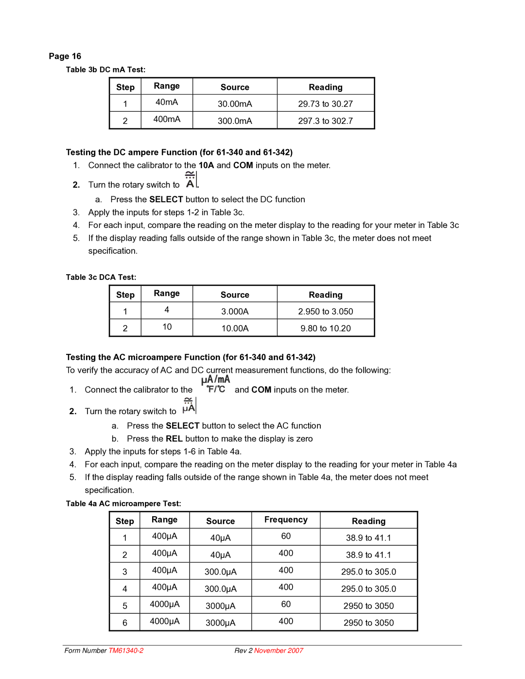
Table 3b DC mA Test:
Step | Range | Source |
1 | 40mA | 30.00mA |
|
|
|
2 | 400mA | 300.0mA |
|
|
|
Reading
29.73to 30.27
297.3to 302.7
Testing the DC ampere Function (for 61-340 and 61-342)
1.Connect the calibrator to the 10A and COM inputs on the meter.
2.Turn the rotary switch to ![]() .
.
a. Press the SELECT button to select the DC function
3.Apply the inputs for steps
4.For each input, compare the reading on the meter display to the reading for your meter in Table 3c
5.If the display reading falls outside of the range shown in Table 3c, the meter does not meet specification.
Table 3c DCA Test:
Step | Range | Source |
1 | 4 | 3.000A |
|
|
|
2 | 10 | 10.00A |
|
|
|
Reading
2.950 to 3.050
9.80 to 10.20
Testing the AC microampere Function (for 61-340 and 61-342)
To verify the accuracy of AC and DC current measurement functions, do the following:
1. Connect the calibrator to the | and COM inputs on the meter. |
2.Turn the rotary switch to ![]()
a.Press the SELECT button to select the AC function
b.Press the REL button to make the display is zero
3.Apply the inputs for steps
4.For each input, compare the reading on the meter display to the reading for your meter in Table 4a
5.If the display reading falls outside of the range shown in Table 4a, the meter does not meet specification.
Table 4a AC microampere Test:
Step | Range | Source | Frequency | Reading |
1 | 400µA | 40µA | 60 | 38.9 to 41.1 |
|
|
|
|
|
2 | 400µA | 40µA | 400 | 38.9 to 41.1 |
|
|
|
|
|
3 | 400µA | 300.0µA | 400 | 295.0 to 305.0 |
|
|
|
|
|
4 | 400µA | 300.0µA | 400 | 295.0 to 305.0 |
|
|
|
|
|
5 | 4000µA | 3000µA | 60 | 2950 to 3050 |
|
|
|
|
|
6 | 4000µA | 3000µA | 400 | 2950 to 3050 |
|
|
|
|
|
Form Number | Rev 2 November 2007 |
