ASSEMBLY
4.CONTROLS
4.1 Description
The boiler connections shall be performed by a qualified professional only.
Strict compliance with these operating and connecting instructions is a precondition for the correct operation of the boiler
9 | 6 | 10 | 7 | 2 | 3 |
|
| 5 | 6 | 7 |
|
|
|
|
| ||
|
| 4 |
| 8 |
|
|
| 3 |
| 9 |
|
|
|
|
| TEST STB | |
|
| 30 |
| AUT |
|
|
| oc |
|
| |
|
|
|
|
| |
| 6,3 AT |
|
|
|
|
BUC5037 | 8 | 4 | 1 |
| 5 |
|
| ||||
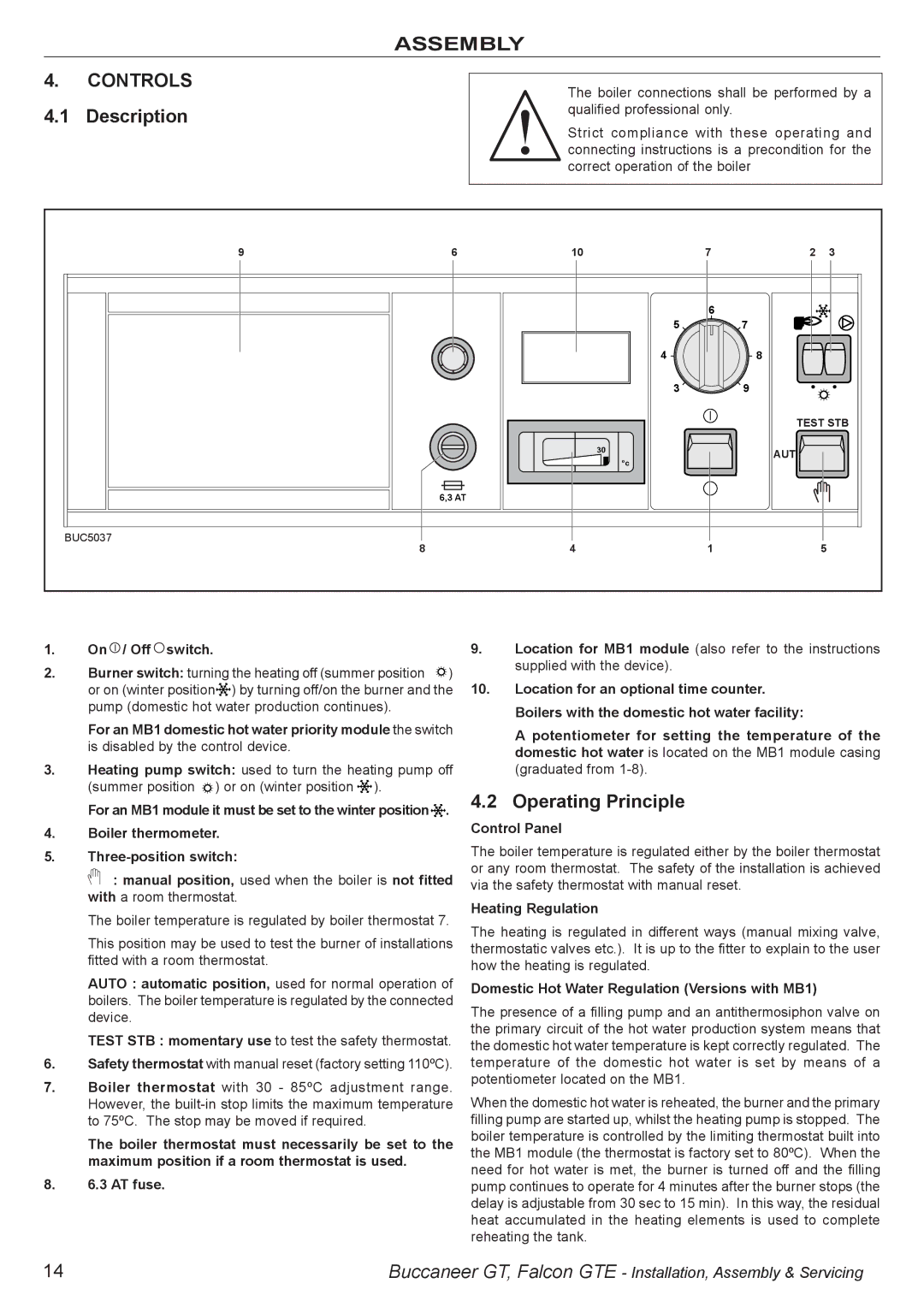
1.On  / Off
/ Off  switch.
2.Burner switch: turning the heating off (summer position ![]() ) or on (winter position
) or on (winter position![]()
![]()
![]() ) by turning off/on the burner and the pump (domestic hot water production continues).
) by turning off/on the burner and the pump (domestic hot water production continues).
For an MB1 domestic hot water priority module the switch is disabled by the control device.
3.Heating pump switch: used to turn the heating pump off (summer position ![]() ) or on (winter position
) or on (winter position ![]()
![]()
![]() ).
).
For an MB1 module it must be set to the winter position![]()
![]()
![]() .
.
4.Boiler thermometer.
5.
![]() : manual position, used when the boiler is not fitted with a room thermostat.
: manual position, used when the boiler is not fitted with a room thermostat.
The boiler temperature is regulated by boiler thermostat 7.
This position may be used to test the burner of installations fitted with a room thermostat.
AUTO : automatic position, used for normal operation of boilers. The boiler temperature is regulated by the connected device.
TEST STB : momentary use to test the safety thermostat.
6.Safety thermostat with manual reset (factory setting 110ºC).
7.Boiler thermostat with 30 - 85ºC adjustment range. However, the
The boiler thermostat must necessarily be set to the maximum position if a room thermostat is used.
8.6.3 AT fuse.
9.Location for MB1 module (also refer to the instructions supplied with the device).
10.Location for an optional time counter. Boilers with the domestic hot water facility:
A potentiometer for setting the temperature of the domestic hot water is located on the MB1 module casing (graduated from
4.2 Operating Principle
Control Panel
The boiler temperature is regulated either by the boiler thermostat or any room thermostat. The safety of the installation is achieved via the safety thermostat with manual reset.
Heating Regulation
The heating is regulated in different ways (manual mixing valve, thermostatic valves etc.). It is up to the fitter to explain to the user how the heating is regulated.
Domestic Hot Water Regulation (Versions with MB1)
The presence of a filling pump and an antithermosiphon valve on the primary circuit of the hot water production system means that the domestic hot water temperature is kept correctly regulated. The temperature of the domestic hot water is set by means of a potentiometer located on the MB1.
When the domestic hot water is reheated, the burner and the primary filling pump are started up, whilst the heating pump is stopped. The boiler temperature is controlled by the limiting thermostat built into the MB1 module (the thermostat is factory set to 80ºC). When the need for hot water is met, the burner is turned off and the filling pump continues to operate for 4 minutes after the burner stops (the delay is adjustable from 30 sec to 15 min). In this way, the residual heat accumulated in the heating elements is used to complete reheating the tank.
14 | Buccaneer GT, Falcon GTE - Installation, Assembly & Servicing |